ioSender V2 User Manual
Everything you need to drive your grblHAL / Grbl machine with ioSender V2 — from first connection to squaring the gantry and running a job. Choose a reading track in the sidebar for a guided order, jump straight to a subject, or press F1 inside the app to land on the page for whatever you're looking at.
Intro to CNC — the big picture #
New to CNC? There's a lot to take in at once — motors, coordinates, probes, g-code, bits, tool changes. This page walks the whole picture once, in plain language, so the rest of the manual (and your machine) stops feeling like alphabet soup. Nothing here is ioSender-specific; it's the mental model every CNC user carries. Read it once, skim it later.
What a CNC actually is
A CNC (Computer Numerical Control) machine moves a spinning cutting tool through a piece of material along paths a computer controls, carving away material to leave the shape you want. It's subtractive: you start with a block or sheet of material — the stock — and remove everything that isn't the part. (A 3D printer is the opposite: it adds material.)
For hobby and small-shop work the common machine is a router or small mill: a motor called the spindle spins a cutting bit, and the machine moves that bit in three directions — the three axes:
- X — left/right, usually along the front beam.
- Y — front/back, along the length of the bed.
- Z — up/down (into and out of the material).
Bigger or fancier machines add a rotary A axis (a 4th axis that spins the stock), but X/Y/Z is the core.
Different shapes of machine
They mostly come in two layouts:
- Gantry router — a flat bed with a bridge (the gantry) that rides front-to-back and carries the spindle. Most hobby routers look like this; great for large flat sheets.
- Moving-table mill — the table slides under a fixed column. More rigid, better for metal, usually smaller work area.
ioSender drives both, plus lathes. The concepts below are the same either way.
Home, machine coordinates, and work coordinates
This is the concept that trips up every beginner, so it's worth getting straight:
- Homing. When you power on, the machine has no idea where it is. Homing drives each axis until it trips a switch at a known corner — that establishes the machine's home position. From then on the controller always knows where it is.
- Machine coordinates (MCS). A fixed grid pinned to the machine, with its origin at home. These never move. You rarely program in them directly — they're used for fixed spots like the tool-change position or a parking location.
- Work coordinates (WCS). Where your part is. You pick a
work origin — typically a corner of your stock and the top surface — and call it
0, 0, 0. Your program is written around that origin. grbl gives you several work coordinate systems (G54–G59.3) so you can store more than one setup.
The key insight: your CAM program is written around a work origin it can't know the real location of. "Zeroing" (usually with a probe) is how you tell the machine where that work origin sits in machine space. Do that well and the part lands exactly where you intend. See Work offsets and Setup.
Anatomy — the major components
Working from the frame up:
| Part | What it does |
|---|---|
| Bed & Y-axis rails | The base and the front-to-back travel the gantry rides on. |
| X beam / gantry | The bridge that moves along Y and carries the Z axis left-to-right. |
| Z carriage | Rides the gantry up and down; holds the spindle. |
| Spindle | Spins the cutting bit — a trim router or a proper VFD-driven spindle. |
| Spoilboard | A flat, sacrificial surface on the bed. You can cut slightly into it, screw workholding into it, and it gives a known flat reference (often surfaced flat by the machine itself). |
| Stepper motors | Turn electrical pulses into precise rotation. (Closed-loop steppers and servos add position feedback so they can't silently lose steps.) |
The motors' rotation is turned into straight-line motion by a drive mechanism, and the type tells you a lot about a machine's cost and precision:
| Drive | Character |
|---|---|
| V-wheels on extrusion | Cheap, light, easy — but the least rigid. Common on entry machines. |
| Linear rails / guides | Hardened rails with recirculating bearings: rigid and precise. |
| Rack & pinion | A gear on a toothed rack — good for long travels on big machines. |
| Lead screw / ball screw | A turning screw drives a nut. Precise; ball screws are low-friction and repeatable. Common on Z and on smaller machines. |
Probes — how the machine "feels" for position
A probe lets the machine touch something and record exactly where it was, instead of you eyeballing it. Four kinds you'll hear about:
| Probe | Used for |
|---|---|
| Touch plate | A conductive plate of known thickness. Touch the bit to it to set Z zero (and sometimes an XY corner). The cheapest option. |
| 3D probe (edge finder) | A spring-loaded stylus that trips when it touches in any direction. The workhorse: finds edges, corners and centres, and measures stock — used to set your work origin accurately. |
| Toolsetter | A fixed button at a known machine location. The tool touches it to measure its length — the key to painless tool changes (below). |
| Touch/edge combos | Many setups use a touch plate or a 3D probe for XY plus a toolsetter for tool length. |
Setup drives these routines for you.
The controller & the grbl language
The controller is the machine's brain — a small board (grblHAL on a Teensy or STM32, or classic Grbl on an Arduino) running firmware that speaks the grbl protocol. It:
- Reads g-code and generates the precise step pulses that move the motors.
- Watches the limit switches and probes.
- Stores its configuration in non-volatile memory (NVRAM) — numbered
settings like
$100(X steps/mm),$110(X max rate),$120(acceleration), homing and limits. These survive power-off. You read them with$$and change them like$100=80.000. ioSender's Settings tab is a friendly front end to all of them, so you rarely type raw$commands.
Command syntax comes in two flavours: g-code (G0/G1
moves, M3/M5 spindle, M8 coolant…) and grbl's system
commands ($$ dump settings, $H home, $X unlock, ? for
a live status report).
Almost nobody hand-writes more than a few lines of g-code — a quick jog, a facing pass, a one-off MDI command. The real program comes from CAD/CAM: you draw the part in CAD, generate toolpaths in CAM, and a post-processor spits out the g-code file for your machine. That file is what you load and run. You'll spend far more time in CAD/CAM than in g-code.
How a milling job flows
A CAM program is organised as operations, each producing toolpaths — the routes the bit follows (clear a pocket, cut a profile, face a surface, carve a relief). When the next operation needs a different bit, the program pauses for a tool change. So a typical job reads like:
rough pocket (¼″ end mill) → tool change → finish contour (⅛″ end mill) → tool change → V-carve detail (60° V-bit)
ioSender streams the file move-by-move, shows a live 3D view of the toolpath, and stops at each tool change so you (or an automatic changer) can swap bits.
Bits — the cutting tools
The bit shape decides what a cut can do:
| Bit | Good for |
|---|---|
| Flat / square end mill | General cutting, pockets, profiles, flat bottoms. |
| Ball nose | Rounded tip for smooth 3D contours and carving/finishing. |
| V-bit | Pointed — sign-making, V-carving lettering, chamfers. |
| Up-cut / down-cut / compression | Flute direction controls chips: up-cut clears chips upward, down-cut leaves a clean top edge, compression does both (great for sheet goods). |
| Surfacing / spoilboard bit | Big flat cutter for flattening the spoilboard or stock. |
Size matters too: diameter (⅛″, ¼″, 6 mm…) and flute length set how fine the detail and how deep the cut — small bits for detail, big bits for hogging material fast.
Why tool changes are the hard part
Every time you swap bits mid-job you risk introducing error, in two ways:
- Z reference moves. A new bit sits at a different length, so "where Z zero is" changes — you must re-establish it or the next cut is too deep or too shallow.
- XY origin can shift. Bump the stock or lose your zero and the whole part moves. Once you've cut some of it, that's usually a ruined workpiece.
Doing this by hand, mid-job, is exactly where beginners lose parts.
Tool change with just a touch plate
Pause → spindle stops → jog clear → swap the bit → set the touch plate on the stock top → jog the bit down until it touches → set Z zero from the plate thickness → remove the plate → resume. It works, but you re-zero Z against the stock surface every change (which may not be perfectly flat), and you must never nudge the XY origin. Lots of little chances to fat-finger it.
Tool change with a 3D probe + toolsetter (automatic)
The trick is measure once, reference forever:
- At the start you set the XY (and top-of-stock) work origin once with the 3D probe, and measure a reference tool length on the toolsetter.
- On every tool change the machine drives to the toolsetter — a fixed, known location — and measures the new bit's length automatically, computing the offset.
Because the toolsetter is at a fixed machine position, the stock origin is never re-touched after that first probe — only the tool length changes, and the machine handles that itself. No re-zeroing by hand, no chance to bump the XY origin. That is how automatic (and even semi-automatic) tool changing eliminates the human error: the risky step simply never happens again. Even if you swap the bit by hand, letting the toolsetter re-measure length keeps Z correct and XY untouched.
Setup sets the work origin with the probe, and the tool-change flow uses the toolsetter to re-measure length on each change — so multi-tool jobs stay accurate without re-zeroing.
What people actually make with a CNC
- Carvings, reliefs & lithophanes — ball-nose finishing of detailed 3D surfaces: signs, decorative panels, backlit lithophanes.
- Cutting complex shapes from sheet goods — profile-cut all the parts for a custom cabinet, puzzles, templates or enclosures out of plywood, MDF or acrylic in one job.
- Small metal parts — brackets, plates and enclosures machined from aluminium (with the right bits, feeds and a rigid enough machine).
- Engraving, PCB isolation, inlays and joinery — fine detail work where hand tools can't hold the tolerance.
That's the whole mental model. Now hit Getting started to meet the ioSender window, then Connect to your machine — the Novice track walks you through the rest in order (use the Next button below).
Getting started #
ioSender V2 is an all-in-one g-code sender for grblHAL and Grbl controllers. It streams your g-code to the machine and gives you everything around that job — connection, jogging, probing, work-offset setup, tool changes, machine commissioning and a live 3D view of the toolpath.
The main window at a glance
A fresh install opens with the full tab strip across the top — nine tabs, left to right. This is a starting point, not a fixed shape. Settings → User Interface → Top-level tabs gives every view a destination — Tab bar, File menu, Tools menu or Not shown — and order within a destination is top to bottom in that list, which is left to right on the tab bar. Changes are applied on restart. That editor is how you get a compact bar: set the views you don't want on it to a menu, leave Setup, Job and Work Order on the bar, and restart. A layout you like can be handed to someone else as a configuration overlay (Help → Support → Export configuration overlay…), which carries the arrangement without your machine settings.
| Tab | What it's for |
|---|---|
| Settings | Every preference, plus the controller's own $ settings. |
| Feeds and Speeds | The cutting-data advisor, and the Fusion add-in import. |
| Setup | The front door: measure your stock, set the origin, and launch a job. |
| Job (the g-code screen) | Load/stream g-code, jog, DRO, feed/spindle overrides, the run strip. |
| Offsets | The work-coordinate table — review, nudge and manage G54–G59.3. |
| SD Card | Browse and run files held on the controller itself. |
| Work Order | Compose a quick job (pockets, drills, contours…) without a CAM round-trip. |
| Machine Setup | Commissioning: the eight-step wizard that describes your machine to ioSender. |
| Lathe Tools | The turning wizards — only enabled when the controller reports lathe mode. |
And the menu bar beside them:
| Menu | What's in it |
|---|---|
| Connect… | Not a menu but a command — opens the connection dialog. Reads Reconnect… once you're connected. |
| File | Load Program, Load / New Work Order — and any view you have moved off the tab strip. |
| Tools | Camera, Machine mirror, Calibration, Probing, Height Map — plus the hardware-gated Tool table, Trinamic tuner and PID Tuner when your controller has them. |
| Help | Wiki, usage tips, a brief tour, video tutorials, error & alarm codes, and Support (restart ioSender, check for updates, roll back a version, open the app data folder, apply or export a configuration overlay). |
A view opened from a menu normally opens in its own window. The exceptions are the four that need the run strip's Generate/Run button and jog pad — Setup, Work Order, Machine Setup and Calibration — which open as a tab for the session instead, because those controls live in the main window and nowhere else. Tabs opened that way carry a close ×; one you placed on the strip yourself does not.
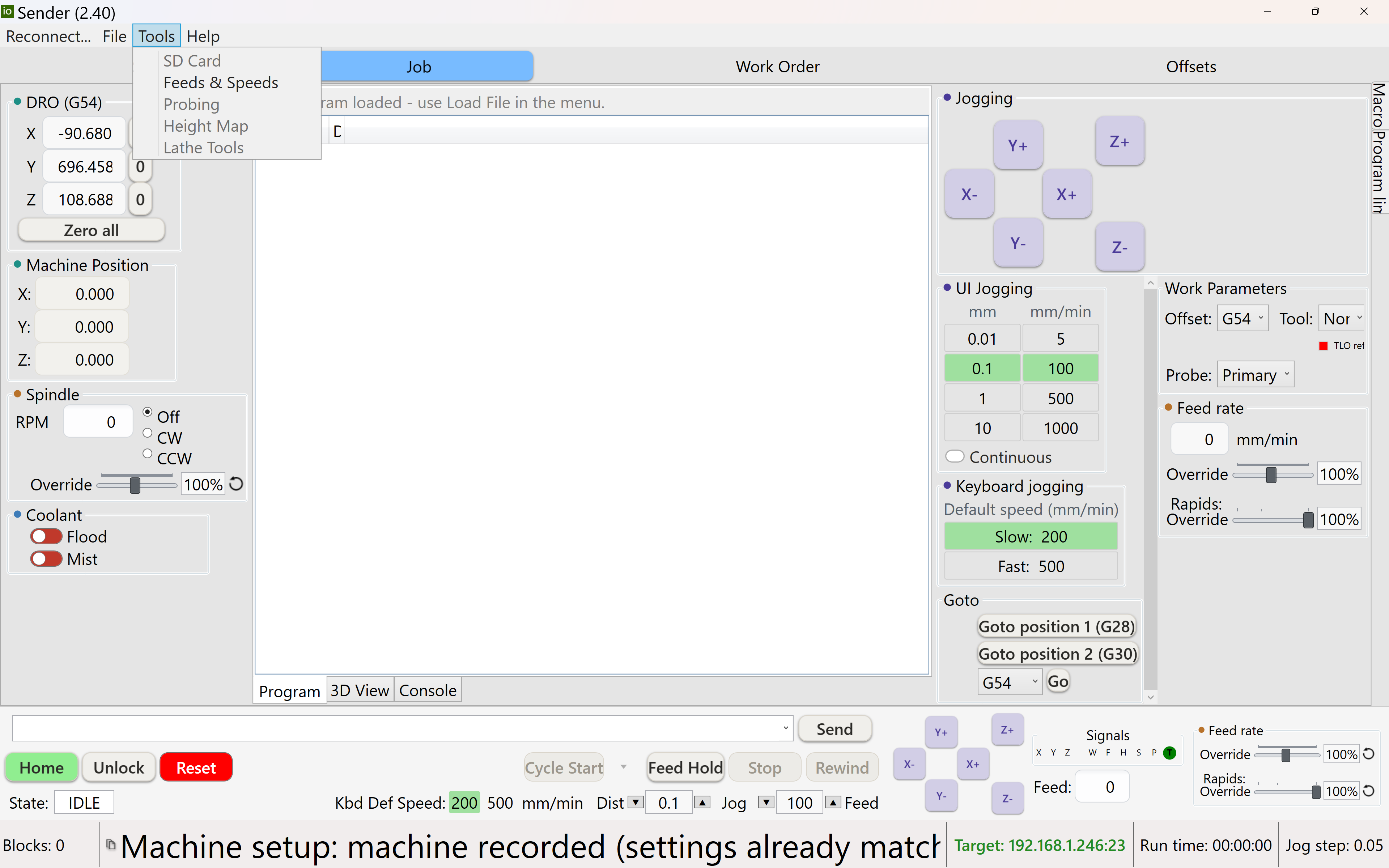
Settings → User Interface → Top-level tabs lets you put any view where you want it — tab bar, File menu, Tools menu, or hidden. Prefer Probing as a tab? Put it back. See Where each view lives. And a keyboard shortcut names a view, not a place, so moving something never costs it its key.
Your first five minutes
- Connect to the controller (serial port or network).
- If it's a brand-new machine, run Machine Setup once — it's a tab on the strip.
- Learn to jog — move the machine safely by hand.
- Load some g-code on the Job tab, use Setup to probe your stock, or compose a quick job in Work Order.
- Know your errors & alarms for when something stops.
Click Novice in the sidebar and the topics reorder into a first-time-user reading path. Use the Next button at the foot of each page to walk it in order.
Connecting to your machine #
Open the connection dialog from the Connect… menu (it reads Reconnect… once you're connected — choosing it drops the current link so you can switch targets). The dialog has three tabs:
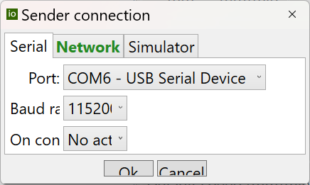
What you're looking at:
- Serial / Network / Simulator tabs — pick whichever matches how your controller is wired; only one is used at a time.
- Port — the COM port your controller shows up as (Windows assigns these; check Device Manager if you're not sure which one).
- Baud rate — the serial speed; must match your controller firmware's own setting (115200 is the near-universal grblHAL default).
- On connect — an optional action to run automatically the instant the link opens; "No action" just connects and stops there.
| Tab | Use when… | You enter |
|---|---|---|
| Serial | The controller is on a USB / COM port (most machines). | The COM port and baud rate. |
| Network | The controller has Ethernet / Wi-Fi (telnet or websocket). | host:port — a hostname or IP and port. |
| Simulator | You have no hardware and want to try the app, or test a job offline. | Nothing — ioSender starts and connects to a bundled grblHAL simulator. |
ioSender remembers your last successful target and can auto-reconnect if the connection drops mid-session. The current target reads at the right-hand end of the menu bar — Connected: TARGET in green, or Not connected in red. It shares that row with the menu, so it hides itself rather than crowd the menu on a narrow window.
What happens on connect
Once the link opens, ioSender runs a handshake with the controller: it reads the firmware build, the axis count, and the available options (probing, WCS rotation, plugins), then enables only the views that controller actually supports — a tab or a menu entry for something your board can't do simply isn't there. This is also when the option-matched simulator is selected, if you're running one.
It also says what it found, in the status log: how many controller settings were read, the controller's identity, version, build and its reported options, and — if the board was already latched in alarm before you connected — that, in as many words. That last one is worth the line it takes: an alarm blocks g-code and filesystem access, so without it the symptom reads as "my macros have gone missing" rather than "the machine is in alarm". "No controller settings were read" is flagged as an error, because travel limits and soft-limit checks are unavailable until you reconnect.
When a connect doesn't go cleanly
- A board that is slow to come back. Opening the port resets many controllers, and a cheap one can take five or ten seconds to boot. Rather than waiting a fixed time, ioSender asks after a couple of seconds of silence whether to keep waiting. It asks rather than simply waiting longer because the two cases cost opposite things: a slow board wants patience, while a wrong port or an unplugged cable wants to be told promptly.
- A controller left in check mode. Grbl answers every
$query witherror:8in check mode, so the capability query cannot succeed there — and neither could a reconnect, because check mode survives one. That used to loop for ever. ioSender now recognises it, leaves check mode and reconnects by itself, and says so in the log. - Capabilities that could not be read. If the link is open but the controller's capabilities never arrived, ioSender does not carry on as if everything were absent — which is what an empty capability set reads as, and is how a board that supports expressions perfectly well once got told it doesn't. It stops and offers two choices: reconnect (which normally fixes it), or stay connected in check mode to look around. Staying is safe only because check mode is then enforced, not merely entered: the machine cannot move until you reconnect, and the log says so.
A first connect opens on Serial. A first-time connect is far more likely to be a USB cable already plugged in than a controller to go discovering for, and the Network tab's Scan button is one click away. The matching setting, Prefer network connection if available in Settings → Application → Main, is off by default — turn it on and a serial connect whose controller reports an IP will switch itself to the network once port 23 answers.
Jogging & the DRO #
Jogging is moving the machine by hand — to reach a corner of your stock, line up a probe, or clear the bit away before a job. It's the first thing to get comfortable with, because everything else (probing, zeroing, tool changes) starts with putting the machine where you want it.
The DRO — reading position
The DRO (digital read-out) shows where each axis is, in two coordinate systems (see Intro → coordinates):
- Work position — relative to your work origin. This is what you usually
watch; it reads
0at the origin you set. - Machine position — relative to the machine's home corner. Fixed, set by homing.
The per-axis zero buttons set the work origin at the current spot — handy for quick manual setups (though probing is more repeatable, see Setup).
Two ways to jog
On-screen jog pad — arrow buttons for each axis, with:
- Distance presets (smallest → largest) — how far one press moves.
- Feed rate — how fast it jogs.
- Continuous — hold to move, release to stop, instead of a fixed step.
- Centre button (the bullseye in the middle of the pad) — rapid to the centre of the machine envelope at safe Z.
- Corner buttons (the four diagonals) — rapid to that corner of the machine envelope at safe Z, held back 20 mm from each limit so you never drive into a switch.
Centre and the four corners are the machine envelope — they don't follow the loaded program's bounding box. That way they mean the same thing whether or not a file is loaded.
If you'd rather have a plain arrow pad, untick Show go-to buttons on the jog pad in Settings → User Interface → General — the centre and four corner buttons disappear and the arrows stay exactly where they are.
Keyboard jogging — arrow keys for X/Y and Page Up/Down for Z. Hold a key for continuous motion; tap for a step. Holding Ctrl switches to a precise step jog of the distance shown as Jog step on the run strip.
There is one rule, and it holds in every window — including dialogs: a jog key jogs and a keyboard shortcut fires, unless you are typing. It's suppressed only by an input field (text box, combo, list, slider or an open menu) where an arrow key already means something; a shortcut carrying Ctrl or Alt still fires even with the caret in a field, because it can't be mistaken for typing. Jogging while a setup dialog is open — lining a fixture up by eye — is the case this was built for. And a key release always stops a continuous jog, whatever has focus by then: that's a moving machine, not a UI detail.
Step vs continuous
Step moves an exact distance per press — use small steps for fine positioning near the work. Continuous covers ground quickly — use it for big moves, then switch to small steps to close in.
Always know where Z is. Raise Z before large X/Y moves so the bit clears clamps and stock, jog at a sensible feed near the work, and remember soft limits will stop a jog that would exceed travel (that's an alarm, not a fault).
ioSender can mirror your jog step/feed settings down to the controller's keypad settings (
$50–$55, from the grblHAL KEYPAD plugin) so a physical pendant jogs the same
way. Configure this under Settings → Jogging.Getting clean, repeatable results #
You can load a file and press Run — now you want parts that come out clean and the same every time. The gap between a rough, torn, or failed cut and a crisp one is almost never the machine; it's a handful of fundamentals. This page is the checklist that separates "it moved" from "it worked." The Intermediate track then walks the reference pages in the order you'd use them on a real job.
1. Workholding — the part must not move
If the stock shifts, the job is ruined, and it's the single most common cause of scrapped parts. Ways to hold work down:
- Clamps — low-profile or step clamps at the edges. Keep them out of the toolpath and preview in the 3D viewer to be sure.
- Screws into the spoilboard — through waste areas; rock-solid for sheet goods.
- Painter's tape + CA glue — tape both surfaces, superglue between: surprisingly strong, no clamps in the way, great for thin/small parts.
- Vise / fixture — for repeat parts and metal.
Hold down near where the cutting forces are, and remember climb cutting can pull the work — clamp against that pull.
2. Feeds & speeds — make chips, not dust
This is the concept that most changes your results. Four numbers interact:
| Term | What it is |
|---|---|
| Spindle speed (RPM) | How fast the bit turns. |
| Feed rate | How fast the bit moves through material (mm/min or in/min). |
| Chip load | Bite per tooth = feed ÷ (RPM × flutes). The number tooling charts quote. |
| Depth of cut (DOC) & stepover (WOC) | How deep each pass goes, and how much of the bit's width engages side-to-side. |
Too slow a feed makes the bit rub — heat, dull edges, burning in wood. Too fast snaps bits. The goal is well-formed chips, not fine dust or a screaming cut. Start from the tooling maker's chart or a feeds-and-speeds calculator, then trust your ears and eyes (below).
Roughing DOC ≈ ½–1× the bit diameter in wood (much less in aluminium); stepover ≈ 40–50% of diameter for roughing, 10–20% for a fine finish. Prefer a ramp or helical entry over plunging straight down.
3. Climb vs conventional, tabs & ramping
- Climb (cutter rotation matches feed direction) leaves a cleaner edge but pulls into the work — great on a rigid machine. Conventional is safer on lighter, flexier machines. Your CAM sets this per toolpath.
- Tabs — when cutting all the way through, leave small tabs (or an onion-skin) so parts don't shift or launch when they free.
- Ramp / lead-in — enter the cut gradually instead of stabbing down; easier on the bit and the finish.
4. Chip clearing & cooling
Recutting chips dulls bits and builds heat. Use a dust boot and vacuum for wood; an air blast or mist/coolant for metal. If a cut is smoking or the chips are brown, something's wrong — stop and check feeds/speeds.
5. A disciplined, repeatable origin
Repeatability comes from setting the work origin the same way every time. Probe it rather than
eyeballing, verify Z zero, and know exactly where 0, 0, 0 sits on your stock.
Setup exists to make this identical run to
run — that's what turns "it worked once" into "it works every time." See also
Work offsets.
Stock secured · correct bit, fully seated · origin probed & Z verified · safe Z retract height · spindle on & up to speed · dust/coolant running · toolpath previewed in the 3D viewer · feed-override and Stop within reach.
Your senses are a live feedback loop: a clean shearing sound and curled chips mean good feeds/speeds; a high whine and dust mean you're rubbing; chatter marks mean too much engagement or not enough rigidity. Adjust the feed-rate override on the fly and note what worked for next time.
Accuracy, calibration & repeatability #
This track is for when "close enough" isn't. You want the machine to land on a number — the part measures what the drawing says, and the tenth part matches the first. Getting there is a discipline: measure, calibrate in the right order, then verify. This page is the philosophy and the sequence; the Machinist track then takes you into the depth pages that do each step.
Three different things people call "accuracy"
| Term | Meaning |
|---|---|
| Accuracy | The machine lands on the correct absolute dimension (a 100 mm move is 100 mm). |
| Repeatability | It lands in the same place every time, even if that place is slightly off. |
| Resolution | The smallest step it can command. Fine resolution ≠ accurate — you can be precise and wrong. |
What steals accuracy
- Wrong steps/mm — every dimension scales off by the same %. Round holes, wrong size.
- Out-of-square axes / poor tram — rectangles come out as parallelograms; surfacing leaves scallops or a taper; diagonals don't match.
- Backlash — slop on a direction reversal; shows as doubled lines or undersized pockets.
- Lost steps — open-loop steppers stalling under load; the machine thinks it moved but didn't. (Closed-loop steppers/servos remove this failure mode.)
- Z reference drift & deflection — inconsistent tool-length referencing, or the machine flexing under cut.
Calibrate in this order
Each step assumes the previous one is done — calibrating out of order means re-doing work.
- Steps/mm (
$100–$102) — command a long known distance, measure the actual travel, correct the number. Do X, Y, Z. Tools → Calibration → Stepper calibration (probe) automates the whole thing by probing a reference block instead, so there's nothing to measure by hand — and Stepper calibration (scratch) does it with a V-bit and calipers when you have no probe. - Squaring & tramming — get the gantry square to the axes
(Tools → Calibration → Squareness uses a
Phil Barrett offset on the ganged axis,
$170+), the spindle perpendicular to the bed (surface a test patch, read the scallops), and the frame square (measure the diagonals of a big rectangle).
Two things about the (probe) version are worth knowing before you start. Clear the existing offset first: the number it proposes is the current offset plus the correction your measurement implies, so measuring on top of an old correction measures the sum of two things. And a single reading cannot tell your square's error from the machine's — do the reversal test, flipping the square and measuring again, or you will square the gantry to your square rather than to a right angle. Both are covered in Calibration. - Backlash — put a dial indicator on each axis, reverse direction, read the lost motion. Fix it mechanically (belt tension, anti-backlash nuts) — that beats software compensation.
- Homing repeatability — home several times and confirm it returns to the same machine position; set pull-off, homing feed/seek, and hard/soft limits in Settings.
- Tool-length strategy — a consistent reference (toolsetter) so a tool change doesn't move Z. Decide your master/reference tool. See Intro → tool changes.
- WCS discipline — use
G54–G59.3deliberately; set offsets withG10 L2/L20; know at every line whether you're in machine or work space. Skew/rotation viaG10 L2 R(Setup uses this) — and see the warning under Work offsets about what follows a rotation write.
Then verify
Calibration isn't done until you've proved it: cut a test — a circle-diamond-square, a calibration cube, or a simple gauge — and measure it with calipers or an indicator. Adjust and repeat until the numbers match.
Closed-loop steppers and servos remove the "lost steps" failure mode, but they don't fix geometry — a machine that's out of square is out of square whether or not it can report position. You still calibrate.
Calibration — the four wizards #
Tools → Calibration holds the tools that measure the machine itself and write the correction back into its settings. There are four, in two pairs — and the pairing is the thing to understand before you pick one:
| Wizard | Corrects | Instrument | Needs |
|---|---|---|---|
| Stepper calibration (probe) | steps/mm,
$100–$102 | Probes a reference block whose true size you already know. | A 3D probe or a touch plate, and a validated Corner Fence fixture. |
| Stepper calibration (scratch) | the same | Scratches candidate lines with a V-bit; you measure them with calipers. | A V-bit and a caliper. No probe, no fixture. |
| Squareness (probe) | the gantry's squaring offset,
$170–$172 | Probes a reference square clamped in the fence. | A probe, the fence, and a decent engineer's square. |
| Squareness (pins) | the same | Drills an L, you drop pins in it and sight a framing square against them. | A drill bit, three pins, a framing square. No probe. |
Each pair is the same measurement by two instruments, and neither member is redundant: the probe versions resolve roughly an order of magnitude finer and cost nothing to repeat, and the other two are the answer on a machine with no probe defined. A tab whose instrument you don't have is disabled, and the selection falls back to its sibling rather than sitting on dead content.
Calibration was a step inside the Machine Setup wizard until it was lifted out whole. The reason is worth knowing because it explains the shape of these tools: all four are Generate-first — they build a program and run it from the run strip — and Machine Setup opens as a separate window, which put each wizard and the button that drives it in different windows. Calibration opens as a tab, with the run strip directly underneath.
$170–$172 exist only where the axis is built ganged and auto-squared,
and only the ganged axis accepts a write — all three show in Settings, which is
misleading. Without the setting both squareness tabs stay useful as gauges: measure the error,
correct it mechanically, measure again. Only the Apply step goes away.Steps/mm without a probe — the scratch method
This is the one calibration with no hardware dependency at all, so it is the one to reach for first on a new machine. Instead of measuring one cut and doing the arithmetic, it cuts several candidate step values at once and lets you pick the winner by measurement.
- Pick the axis; its current steps/mm is read from the setting and shown.
- Set the Span (how far apart the two marks of a pair are — longer is a better lever), the Delta in steps/mm between candidates, and the number of Test points. The panel states where the pattern reaches, whether it fits the envelope, and the smallest stock it will sit on.
- Generate and run. The program scratches one numbered pair of marks per candidate.
- Measure each pair with calipers, type the reading into the Measured column, and the row whose implied steps/mm is closest goes green. Save steps/mm writes that row's value to the setting.
Steps/mm cannot be changed part way through a program, so the candidates are not set — they are simulated. Each pair is commanded at
span × candidate ÷
      current
, which produces motion physically identical to running with that steps/mm. Measuring the
spacing therefore measures the candidate, with nothing to reset afterwards.- The two marks of a pair have separate depths, which looks fussy and is not: the reference surface is not flat, and a spoilboard that dips more than the cut depth across the span marks one end and misses the other — and a pair with one mark missing cannot be measured at all. Depth does not affect the result; the measurement is the spacing between the two line centres, and a V-bit's centre is under the spindle axis at any depth.
- Reference the loaded bit at the puck is on by default and should stay on unless the bit arrived through a tool change in this same session. Work Z0 means "the stock top" only for a tool that has a length offset; a bit fitted by hand without one cuts at the previous tool's depth.
Squareness by probing — and the reversal test
The pin method makes the machine the writer and a framing square the reader: it drills its own idea of a right angle and you judge the gap by eye. Squareness (probe) inverts that — the square is the artifact and the probe is the reader. It probes three corners of the square through the same corner-probing macro Setup uses, and turns the result into a squaring-offset correction.
The inversion buys three things, and they are why this is the method to use if you have a probe at all:
- Resolution. A gap sighted at a pin is good to a few hundredths of a millimetre; probe repeatability is an order better. Over a 600 mm blade that is thousandths of a degree rather than hundredths.
- A free iteration. Applying a correction changes the gantry angle — so the L you just drilled sits at the old angle and cannot verify the new one. Every pin iteration costs a fresh L, a bit, a touch-off and more spoilboard. A re-probe costs two minutes.
- The reversal test, which is the only way to know your square is any good.
What one measurement gives you is square + machine, added together and inseparable — so correcting it to zero does not square the gantry, it squares the gantry to your square, errors and all. Flip the square over and measure again: mirroring reverses the sign of the square's own error and not the machine's, so the two averages separate them — square = (normal + reversed) ÷ 2 and machine = (normal − reversed) ÷ 2. Both halves must be measured at the same squaring offset with no homing in between, or they describe two different machines.
The flip is physical, and the panel tells you how to do it: a mirrored L cannot lie with both arms in the same quadrant, so the Reversed orientation registers the far end of the blade in the fence and puts the heel out to the right. The result is then stored as the square's own error and subtracted from every later reading — which is the real payoff, because the reversal is a property of a physical object and never has to be repeated. If a reversal was done in an earlier session you can type its figure straight into the square-error field.
Applying a squareness correction
- Clear the offset first, once, before the first measurement — the Clear button
zeroes
$17xand re-homes, so what you then measure is the machine's raw mechanical error rather than the sum of the error and an old correction. - Choose the ganged axis (usually Y), the probe, and the fixture the square is clamped in. Give the arm lengths and the square's actual measured thickness — that thickness sets how far below the top the side faces are probed, and being out by much has the probe seeking past the edge through open air.
- Measure, then Apply offset and Re-home. The proposed number is the current offset plus the correction the measured skew implies, and it is editable.
- Re-measure. That is the step, not an optional check.
Which way a positive offset racks the gantry depends on which rail your firmware's ganged motor drives, and nothing reports that. If the first Apply makes the measured skew bigger rather than smaller, tick Invert correction direction and apply again — then leave it ticked. And watch for the other end of it: if two successive Applies stop moving the measurement, the offset has run out of authority and what is left is mechanical. Chasing it with an ever-larger number does nothing.
Fitting the probe is a tool change, and a bit fitted by hand has no length offset of its own. With Set TLO reference ticked the run touches the puck first and restores the offset afterwards. It is not for the measurement's sake — this is an XY angle and a tool length cannot tilt it — but without it the run works against, and hands the machine back, whatever offset the previous tool left.
The Job screen — running g-code #
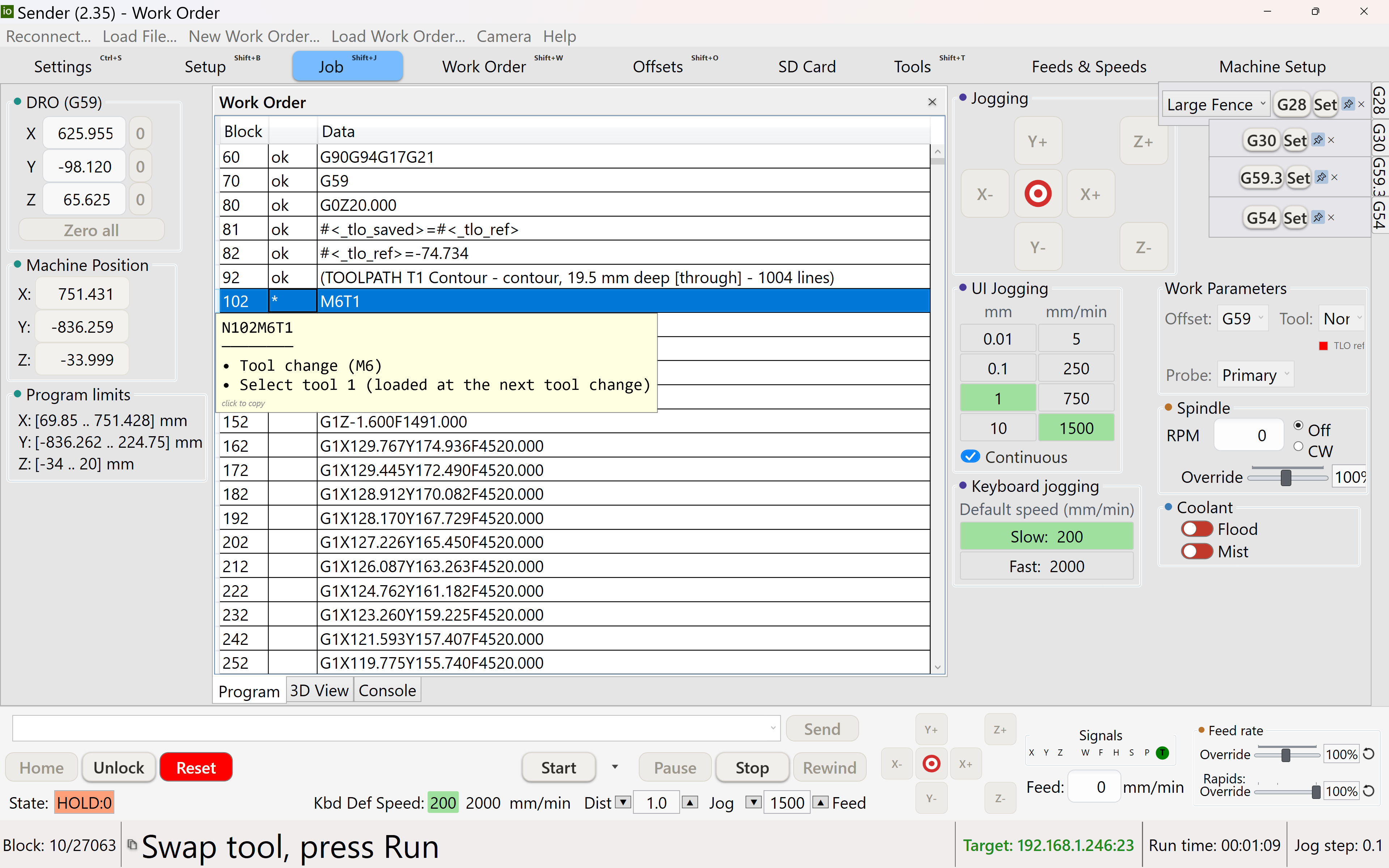
What you're looking at:
- DRO (top left) — the live X/Y/Z position, with a per-axis zero button; see Jogging & the DRO.
- Machine Position — the same position in fixed machine coordinates rather than your work origin.
- Program limits — the loaded program's own footprint (min/max per axis), so you can sanity-check it fits your stock before running.
- Coolant — manual Flood/Mist toggles, independent of whatever the running program itself commands.
- The g-code list (centre) — the loaded program, line by line, with the current line highlighted as it runs. Hover any line for a plain-English tooltip explaining exactly what it does (shown here for
T1M6— "Select tool 1", then "Tool change (M6)", in the same left-to-right order the words appear in the line) — click the tooltip to copy the line. - Jogging / UI Jogging / Keyboard jogging (right) — the on-screen jog pad plus the distance/feed presets each jog step uses. The pad is the widest thing on that side; if the run strip's own compact jog controls are enough for you, untick Show the jog pad on the Job tab in Settings → User Interface → Job tab layout and the panels get that height back. Keyboard and game-controller jogging are unaffected either way.
- Work Parameters & Spindle — the active work offset and tool, and manual spindle RPM/direction/override controls.
- The fixture panel (far right, vertical) — quick-jump buttons to named machine positions like G28/G30/G54.
- The run strip (bottom, spanning the window) — everything a running job needs, in one place. On the left: the Run button and its mode dropdown, Feed Hold, Stop, Peek, the block counter and an MDI button that opens the console ready to type; below them Home/Unlock/Reset with the machine State beside them, then the coolant toggles and the jog distance/feed presets. On the right, three groups — Jogging, Signals and Overrides — see below. There is no longer a status bar along the bottom of the window: everything it used to show is here or on the menu bar.
Two things on the strip worth knowing about
- State is colour-coded and clickable. The field beside Home/Unlock/Reset is the controller's own state — Idle, Run, Hold, Alarm, Door — with a background colour that says it at a glance and a tooltip that spells it out. Right-click it for three recovery goals: Reset, Reset and Unlock, and Reset, unlock and home. Each one runs only the steps the alarm you actually have needs; it will not reset if the alarm clears without one. Elapsed job time sits next to it while a job is running, and stays there afterwards showing the last run's time. It is absent rather than reading 00:00:00 when there has been no job.
- Signals is four rows of lamps: Limit, Steppers, Probes and the TLO ref value. A lamp is the axis or signal letter itself, dim when clear and red when asserted. Under Probes, P and T are the two selectable probe inputs rather than two signals — only one is routed at a time and the other is struck through; double-click the struck-through one to select it. TLO ref is blank, not 0.000, until a tool-length reference has actually been set.
The Job screen is where you load g-code, watch it, and run it. It's the home base you return to for every job.
Loading a program
- Load File... — open a single g-code file (
.nc,.gcode,.tap…) using the button on the program-view header (or drag-and-drop a file onto the list). - Load Folder... — open a whole folder of per-operation
.ncfiles (as a CAM post often produces) and combine them into one ordered program, using the program-view header button (or drag-and-drop a folder onto the list). - Work Order — press Run on the Work Order tab and the program it just compiled loads here as the real, active job — not a preview. Whatever was loaded before is restored once the run ends.
Large files and folders load on a background thread, so the window stays responsive while a big program parses. In ioSender a program is a program: whether it came from a file, a folder, or Work Order, it shows in the same g-code list, runs the same way, and updates the same live per-line status as it executes. The program-view header's title names what's loaded (a filename, or "Work Order" for a generated run).
The load says what it is doing — "Loading name…" while it reads, then "Loaded name — 220,144 lines in 3.1 s" when the list is bound. A file that big used to sit behind a wait cursor long enough to read as a hang; now it reports, and the number it reports is the one you actually waited, bind and all. The Data column shows the g-code from the start rather than opening collapsed to nothing.
Press Run on a program whose X or Y footprint spans further than
$130/
$131 say the machine travels, and ioSender stops and asks — naming the axis, the span and
the travel in millimetres. If soft limits are off it says so in as many words:
the controller will not stop it, the axis will run into its end stop and stall there. Answering
No refuses the run and writes the reason to the status log. An axis whose
travel is not configured is left alone rather than being given an invented limit.ioSender parses your program to draw it and to work out its footprint — but it is not the authority on what is valid g-code, the controller is. Every block this parser cannot make sense of is streamed verbatim rather than dropped. That matters because the opposite behaviour edits your program silently: a
G59.3 lost from a run once left the next line's G0 Z0
executing in the still-active G54, which turned "go to the top of the toolsetter" into a
128 mm plunge. A line the controller cannot execute comes back as an error, the run stops, and you can
see which line it was.!, ~ and ? are grblHAL realtime characters. The
controller lifts them out of the stream before anything is parsed, so they act wherever
they appear in a line — including inside a comment. ! is feed hold, ~ is
cycle start, and ? asks for a status report. A line that begins with one
is held back by ioSender and logged, but a (Watch out! deep pass) comment in your own file
will still stop the machine mid-cut — and a stray ~ will start it moving again. Keep all
three out of g-code comments. Comments ioSender generates itself are stripped of them.Programs that ask you a question
A file can carry its own fields. Any comment of the form
(PROMPT name, default[, label]) becomes a box in a small form that ioSender
shows as the file loads, and the answers are installed before a single line is parsed.
One square.nc then covers every size of square you will ever cut.
- Asked at load, not at Cycle Start, so the answers are in place for the 3D preview too — what you see drawn is the geometry you are about to cut, not the defaults.
- Cancel keeps the defaults and still loads. "The defaults are fine" is the common case and a refused load would punish it.
- Every field is asked once, in one form, however many times the file references it. On a controller with no expression support the references are folded to the answers as the file loads, so the arithmetic never reaches the wire — which is what makes a parametric program work on plain Grbl.
The g-code list & the 3D view
The loaded program appears as a scrolling line list beside the live 3D viewer, which draws the whole toolpath and highlights progress as it runs.
By default a tab strip at the bottom switches between the list, the viewer and the console. Tick Show 3D view in split screen on Job tab in Settings → User Interface and the list and the viewer sit side by side with a draggable splitter instead — code and toolpath at once. The space comes from the jog pad and the Feed/Spindle/Outline columns, which give it up; the left panel column stays, and the splitter's position is remembered. The console goes with the tab strip, and loses nothing by it: the run strip's MDI button opens the real console in its own window.
The run strip's run controls
The main button is labelled Run, with a small dropdown beside it that picks which mode the next press starts in. Whichever mode you last picked becomes the button's own label, so the button always reads exactly what it's about to do:
| Mode | Does |
|---|---|
| Run | Start the loaded program for real — or resume after a feed hold. |
| Dry Run | Rehearse the program: Z stays offset clear of the stock, spindle/coolant are forced off, and tool changes are skipped — watch the whole toolpath run without cutting, spinning, or pausing for a tool swap. |
| Check Run | Starts the controller's own check mode ($C), which parses the program without moving anything, to validate it before a real run. $C isn't armed until you actually press Run — picking Check Run alone doesn't send anything. |
| Simulate | Temporarily switches to the bundled grblHAL simulator, runs the program there, then reconnects to your real controller once it finishes or is aborted — a way to preview a job with nothing connected, or with the machine unavailable. |
Whichever mode you ran reverts back to plain Run once the job ends, so the button never gets stuck offering to repeat a Dry Run/Check Run/Simulate pass by accident.
| Control | Does |
|---|---|
| Feed Hold | Pause: the machine decelerates smoothly and holds position (spindle keeps running). Run resumes. |
| Stop | End the run. |
| Peek | Pause at the end of the current block, park at G30 with the spindle off so you can look at the work, then press again (it reads Resume) to go back and carry on. See below. |
| Reset | Soft-reset the controller — stops motion, clears an alarm, and returns to a known idle state. |
| Optional stop | Honour M1 optional-stop pauses in the program. |
Neither is permanently on the strip. Feed Hold appears whenever the machine can move — running, holding, jogging, mid-tool-change or with the door open — including while you are only jogging, since a feed hold during a jog decelerates and cancels it. Stop is about a job, so it appears exactly when there is something streaming to stop. Peek is the same: it is on the strip while a program is streaming, and while you are parked, and not otherwise. A greyed-out button still asks to be read; these simply aren't there when they'd mean nothing.
Feed Hold is a graceful, resumable pause — use it first. Reset is the hard stop that also clears alarms but ends the job. Keep a hand near Feed Hold / Stop whenever you start a cut, and near the physical E-Stop for a true emergency.
Peek — step away from a paused job and come back
Mid-job you want to look: at the cut, at the chips, at whether that tab is still holding. The choice used to be Stop and lose the run, or Feed Hold and peer past the gantry with the tool sitting in the work. Peek is the third option — it is the tool-change pause without the tool change.
Press it and ioSender stops feeding lines, lets the controller finish what it already has, then parks
the machine at G30 with the spindle off. Look at the work as long as you
like. Press the same button again — it now reads Resume — and the machine goes back:
Z clear first, then X and Y, then the spindle restarted and given time to come up to speed, then the
plunge, and the program carries on from the block it stopped at. Cycle Start resumes too.
Two things about it surprise people, and both are deliberate:
- It takes effect at the end of the block, not instantly. Usually well under a second; on one long cutting move it is that move. That delay is what makes it safe — nothing is cut short, no reset is needed, and the controller never loses its parser state, so there is nothing to rebuild on the way back. Feed Hold remains the immediate stop and is unchanged.
- It parks at
G30, not at machine home. SetG30somewhere you can actually reach the work from — that is what makes Peek useful on your machine rather than just out of the way.
Peek refuses, and says why, in two cases. It is not offered for an SD card job: the
controller streams those itself, so the sender cannot pause the flow. And it needs a controller with
expression support, because the park reads the stored G30 parameters. It is
unbound by default — give it a key under Settings → Keyboard & Controller → Program,
alongside MDI and Status. It is not a menu item, on purpose: the menu bar is disabled while a job streams,
which is exactly when you want this.
Overrides
Tune a running job without editing the g-code: adjust Feed rate, Rapids and Spindle live. Overrides are how you dial in feeds by ear on the fly — see reading the cut.
On the run strip each row is a − value + stepper, and the bar behind
the digits is the override itself: how far it fills says how much, and its colour says which way.
Half-full and green is 100% — the program's own feed — so a glance across the strip tells you whether the
machine is running what you asked for.
- Feed rate and Spindle show the live value, not the percentage. The buttons step the override by 10%; double-click the value to put it back to 100%. Feed rate is read-only (it comes from the program); spindle RPM you can type into and press Enter to set.
- Rapids is a percentage, because there is no "current rapid rate" to show — only the setting. grblHAL offers three values and no others: 100 / 50 / 25. A single click on the value resets it.
- Under them, spindle direction — Off / CW / CCW. These follow what the machine
reports, so an
M3typed at the MDI or a direction change inside the program moves them too.
The run strip's Feed: readout drops the mm/min · in/min label — on that strip the room is better spent on digits — and states the unit in its tooltip instead. The full Feed rate panel still shows its unit inline, and both readouts now grow to fit a five-digit rate rather than clipping it.
The toolpath outline
A program with tool changes in it does not arrive as one flat wall of lines. The g-code list groups itself into collapsible toolpath sections, so what you see first is a summary of the job — one row per toolpath, each showing its name, its line count and its own estimated run time. Groups start collapsed; click a chevron to open one.
- Where the sections come from. If the file carries the ioSender Fusion add-in's own section markers, those are used. Otherwise ioSender derives the sections from the tool changes — which means an ordinary CAM post, or a file you wrote by hand, gets an outline too. Markers win where a file has both.
- Program start and Program end are sections in their own right:
everything before the first tool change (the preamble, the modal setup, the initial positioning), and
the wind-down after the last cut (spindle stop, park,
M30). A program whose last toolpath emits no spindle stop simply has no Program end section, rather than a guessed one. - Naming — worth knowing for your own files. A section is named after the
tool where the program declares one ("T2 — 6 mm flat endmill"), because at a tool change the
thing you need to know is which bit to fit. Failing that, a comment immediately above the tool
change becomes the toolpath's name — the first comment of an unbroken comment run, so an
operation name above a tool description wins. That is opt-in behaviour you can use in your own posts
and hand-written programs: put
(Roughing pass)on the line above theM6and the outline says so.
Starting partway through
After a broken bit, a stopped job, or a toolpath you want to repeat, you do not have to run the program from the top. Right-click a toolpath's group header for the two commands that do this properly:
| Command | Runs |
|---|---|
| Start from this toolpath | Program start, then from this toolpath to the end of the program. |
| Run just this toolpath | Program start, this toolpath, then Program end. In that order — the job still winds down properly. |
Both ask first, naming the toolpath and saying exactly which sections will run. The important part is that both run the program's own preamble, not a synthetic one: started mid-program, a toolpath sets no units, no plane and no work offset — it inherited them from lines you are about to skip. Running Program start re-establishes the real thing the program's author wrote. If the file has no Program start section — its very first block is already inside a toolpath — the prompt says so, and warns that units, plane and work offset will be whatever the machine currently holds.
The program list's own right-click Start from here begins at the selected line. It re-establishes distance/feed mode, plane and units — and nothing else. It does not restore the work offset, the tool-length offset, the feed rate or the spindle, and the confirmation says as much. Where the program has an outline, Start from this toolpath is the supported route and the safer one.
What actually happened — the Status window and the log
ioSender narrates itself. Loading a file, a connection and how many settings it read, a run starting and ending, a Generate, a setting change, a dialog and the answer you gave it — each is recorded as it happens. There is deliberately no permanent status line spending a strip of screen on the latest message; instead, only a message that matters puts itself in front of you, and everything is kept. Two ways to it:
- The Status window holds every message since launch. The run strip's Status button opens it, and it also opens itself — but only for an error or an alarm, and it dismisses itself again after a few seconds so a routine message never takes the screen. How long it lingers is a slider in Settings → User Interface; shortening it loses nothing, because nothing is ever dropped from the log behind the button. A window you opened does not close itself, and an arriving message refreshes it without starting a countdown on it.
- The status log on disk —
%AppData%\ioSender\logs\status_<timestamp>.log, withlatest_status.logpointing at the current run. Every message is written there as it happens, tagged with whether it was an error and whether it came from ioSender or from the controller as an[MSG:]. That last distinction is the one this log gets opened to answer: which of these did the machine actually say?
The window's own list is capped and drops its oldest lines on a long session; the file does not. When something went wrong an hour ago, the file is the one to open.
Right-click → Transform in the program list can rotate the program, convert arcs to lines, add drag-knife moves and more before you run — handy for fitting a job to your stock orientation.
Double-click the Console tab to pop it out into its own floating window — handy for watching traffic on a second monitor while you work the Job screen. F12 opens it with the caret already in the input box, ready to type, and Esc closes it — the same key that dismisses every other floating window here. The run strip's MDI button does the same thing. Rebind it, or give Status a key too, under Settings → Keyboard & Controller → Program.
It has a Search box: every match in the log is highlighted at once, not just the one you are on, with a count beside the box — Enter or F3 steps to the next match and F4 to the previous. The A−/A+ steppers set the log's text size and the MDI input's separately, which matters when the log is across the room and the line you are typing is under your nose. Right-click the log for Clear all, Clear up to here and Save.
Setup — measure stock & set the origin #
Setup (formerly called "Start Job") is the guided front door to running a part. Instead of jogging around and zeroing by eye, you let the machine probe your stock: it finds the real size and position, optionally corrects for how the stock sits skewed on the table, sets the work origin, and takes a tool-length reference.
Setup is a single, shared fact about the machine — not something you redo per program. It's the same
tab and the same saved state whether you go on to run a loaded .nc file from the
Job tab or a program you compose in Work Order; there's no
separate "setup" step duplicated inside Work Order. Run Setup once, then use either.
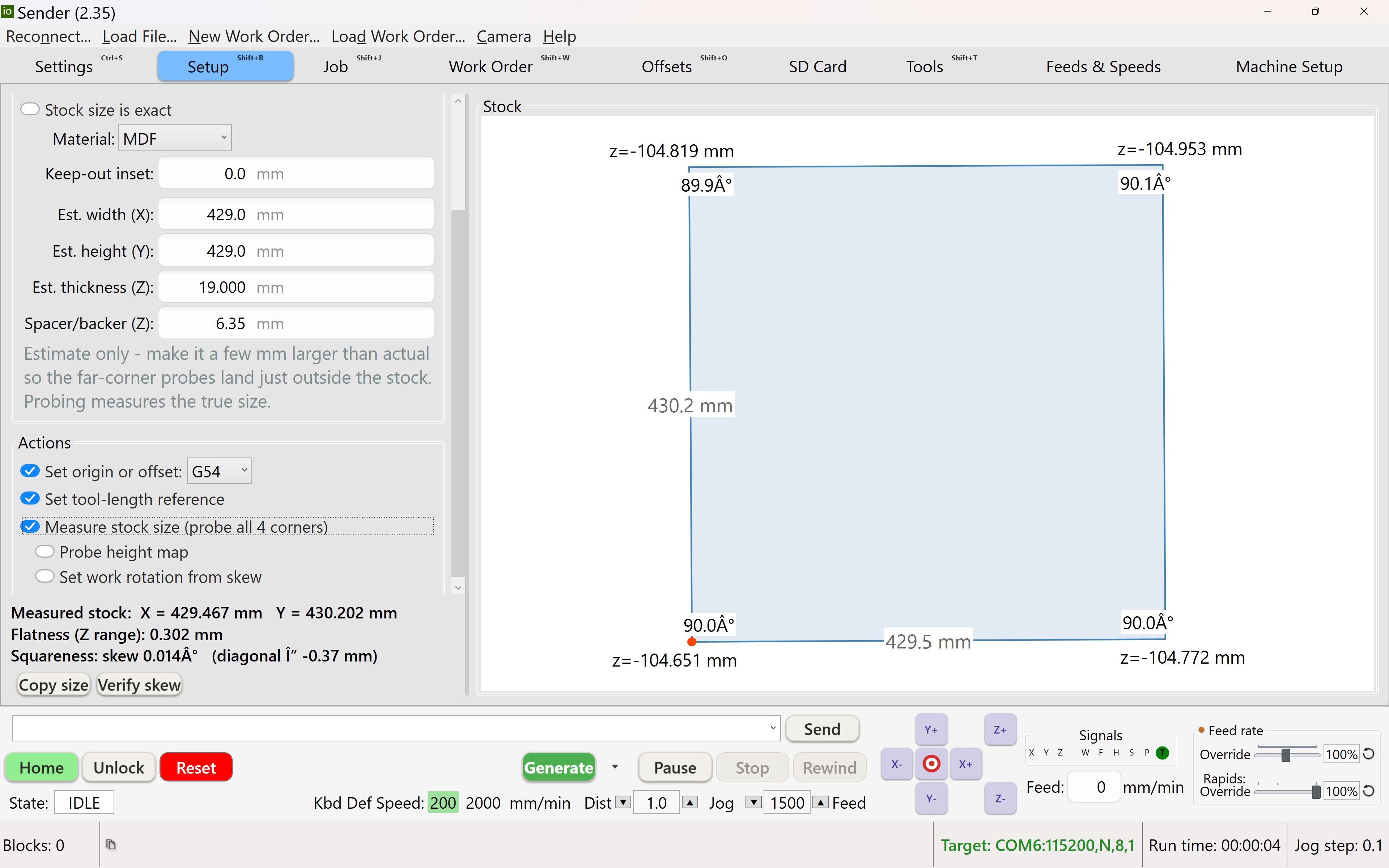
What you're looking at:
- Setup (top group) — pick the physical Fixture you clamped the stock against (defined in Machine Setup's Fixture definitions, or the built-in Dynamic fixture below) and which Probe to use — a 3D probe, or a Touch Plate (electrical continuity). Safe Z delta sets how high the probe retracts between touches.
- Geometry — only shown when the Dynamic fixture is picked: choose External/Internal and Is Circle with clickable corner/edge/centre picker grids, so a one-off feature that doesn't have a saved fixture position can still be set up here without leaving the tab.
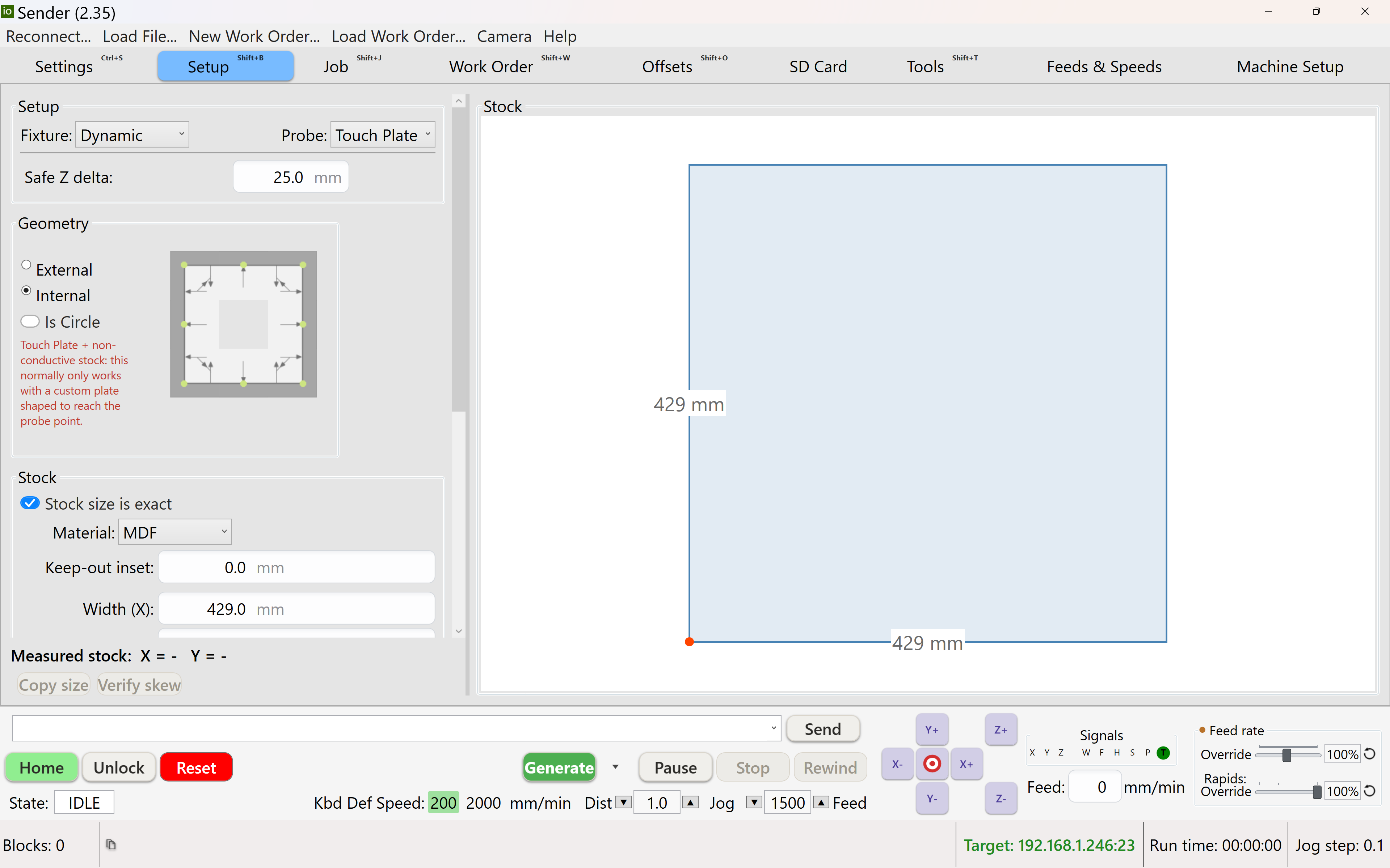
- Stock — the nominal Width/Height/Thickness you already know (from your CAM file or a tape measure); tick Stock size is exact only if you trust those numbers precisely, since it changes how aggressively the probe searches for the real edge. A Material picker here also drives probing rules (see the conductive-stock callout below) and feeds the chipload-based feeds/speeds advisor used elsewhere (e.g. Work Order).
- Actions — Set origin or offset picks the destination: any work-coordinate slot G54–G59, or G92 for a temporary offset; Set tool-length reference also probes the current tool's length at the same time; Measure stock size probes all four corners; Probe height map (once stock is measured) probes a grid over the stock and applies the resulting surface compensation to the run; Set work rotation from skew applies the measured skew as a work-coordinate rotation.
- Measured stock / Flatness / Squareness — filled in once you've run a probe: the real measured size, how flat the top is, and how far off-square (skewed) the stock actually sits.
- The Stock diagram (right) — a live schematic of the four probed corners, with each corner's angle and Z height plus the diagonal measurements, so you can see at a glance how square and flat the material really is.
- Copy size / Verify skew / Scribe square — copy the measured size back into the nominal fields, re-check the frame the measure computed (see below), or cut a test rectangle you can measure with calipers.
- The green Generate/Run button at the bottom of the window builds (then runs) the job once you're happy with the setup.
The steps
- Stock — enter your nominal stock size, or let the probe measure it.
- Measure stock size (probe all 4 corners) — the machine touches each corner so it knows the true X/Y extent and where the stock actually is.
- Set work rotation from skew — if the stock isn't perfectly square to the axes, ioSender computes the small rotation and applies it as a work-coordinate rotation, so you don't have to dial the material in by hand.
- Set tool-length reference — probes the tool so Z is referenced correctly.
- Set origin in — choose which corner (or centre) of the stock the g-code origin sits at, then press Generate on the run strip at the bottom of the window (the shared Run button reads "Generate" while this tab is focused and nothing's built yet).
Generate, then look before you run
Generate does not run anything. It builds the program, makes it the loaded job — the real one, in the Job tab's own program list — and takes you there to look at it. Read it, see it drawn in the 3D view, check its footprint against your stock, and then press Run. The program a Setup step builds gets the same treatment as one you loaded off disk, because it is one.
Changed your mind? Esc discards the handed-off program, gives you back whatever was loaded before, and returns you to the tab that built it. It only does this while a handoff is actually outstanding and the job has not been started — Esc is not a Stop, and it refuses while something is running.
A four-corner measure is remembered and comes back next time you open ioSender — and the readout names the date it was taken: "Restored from the measure of Fri 19 Sep 14:22 — re-measure if the stock has moved." It says so because those numbers describe stock that may have been re-clamped or replaced since, and Verify skew writes a work origin and rotation from them. A partial measure is never saved — but it never erases a complete one either.
Verify skew visits the six points of the measured frame to check it before you commit to cutting. The Touch corners checkbox decides how:
Ticked — it crosses to each point at machine top and then probes all the way down. The descent is the probe, which is the point: a probing move stops on contact, so a tool-length offset left over from a different tool can only make it touch high or miss — it cannot drive into the stock. Each corner targets its own measured top, so the board's own flatness is followed rather than assumed away.
Unticked — a fly-over: the same six points are visited, nothing descends and nothing is probed, and you sight the tip against each corner by eye. It needs no probe defined or fitted at all (and the box clears itself, disabled, when you have no 3D probe). It sights from 2 mm above the stock top, inset by the tool radius so the tool isn't covering the very corner you're looking at — or pick a V-bit from the dropdown and its point sits exactly on the corner with no inset. Each pair of back corners is crossed at that height, so the gap between the ideal point and the probed one is something you watch happen rather than compare from memory.
Every other check here judges a point, and a point can only be judged by eye. Scribe square cuts a rectangle inset 10 mm from every edge of the measured frame, 0.25 mm deep with the selected V-bit, turning an angular error into a taper you read with calipers over the full length of the stock: get the rotation right and the gap to the front edge is a constant 10 mm end to end; get the sign wrong and it tapers by twice the length times the sine of the angle — millimetres, unmissable with a rule. The panel states the numbers to expect, so they are predictions to check rather than just output. It has its own button, deliberately not a third mode on Verify skew: this one runs the spindle and leaves a permanent mark on the part, and that must not sit one checkbox away from a check that touches nothing. It needs all four corners probed and a V-bit selected, and it follows the probed surface — the cut depth is interpolated from the four corner tops, so a stock that is a few tenths out of flat still scribes an even line rather than deep at one corner and missing at another.
A Touch Plate probe reads electrical continuity, so it needs a conductive path. ioSender reads conductivity from the Material you picked in Stock (aluminium/brass/steel are conductive; wood-based materials aren't) rather than a separate checkbox. Probing a Dynamic Internal/Is-Circle feature on non-conductive stock with a Touch Plate shows a warning rather than a hard block — a custom-shaped touch plate can still reach those points.
Picking a Touch Plate always applies its thickness and lip offsets, whatever the stock is made of. That's the right test, because the probe circuit closes between the bit and the plate — both metal — and never through the material underneath. So probing conductive stock with a plate (thin aluminium sheet, say, too thin for a reliable direct stylus touch) is an ordinary workflow and compensates correctly. Stock conductivity only drives the reliability warning above.
Setup writes a controller-side
start_job.macro and performs an automatic 3D (or touch
plate) probe as part of the sequence. It must land on the Job tab to bootstrap the controller
handshake. The work rotation uses grblHAL's G10 L2 R, and the measured skew is
applied as itself, not negated: work +X maps to machine direction
(cos θ, sin θ), so aligning the work frame to a stock edge at +θ takes R+θ. The
origin written alongside it is counter-rotated, because grblHAL rotates the sum of
offset and position — the pivot is machine zero, not the WCS origin, so a raw origin
would land at R × C instead of the corner that was probed, by an error that grows with how far
out on the table the stock sits. There's no completion gate: nothing hides other tabs until Setup has "provably" run —
Generate simply asks, once, whether to proceed on the currently cached origin and tool-length
reference.Work Order — build a job without a CAM round-trip #
Work Order is a top-level tab for jobs that don't deserve a trip out to CAD/CAM and back — drill a hole, cut a pocket, chamfer an edge, two minutes at the machine instead of a design session. You describe the job as a tree of toolpaths and operations; ioSender compiles it into an ordinary g-code program and runs it exactly like a loaded file.
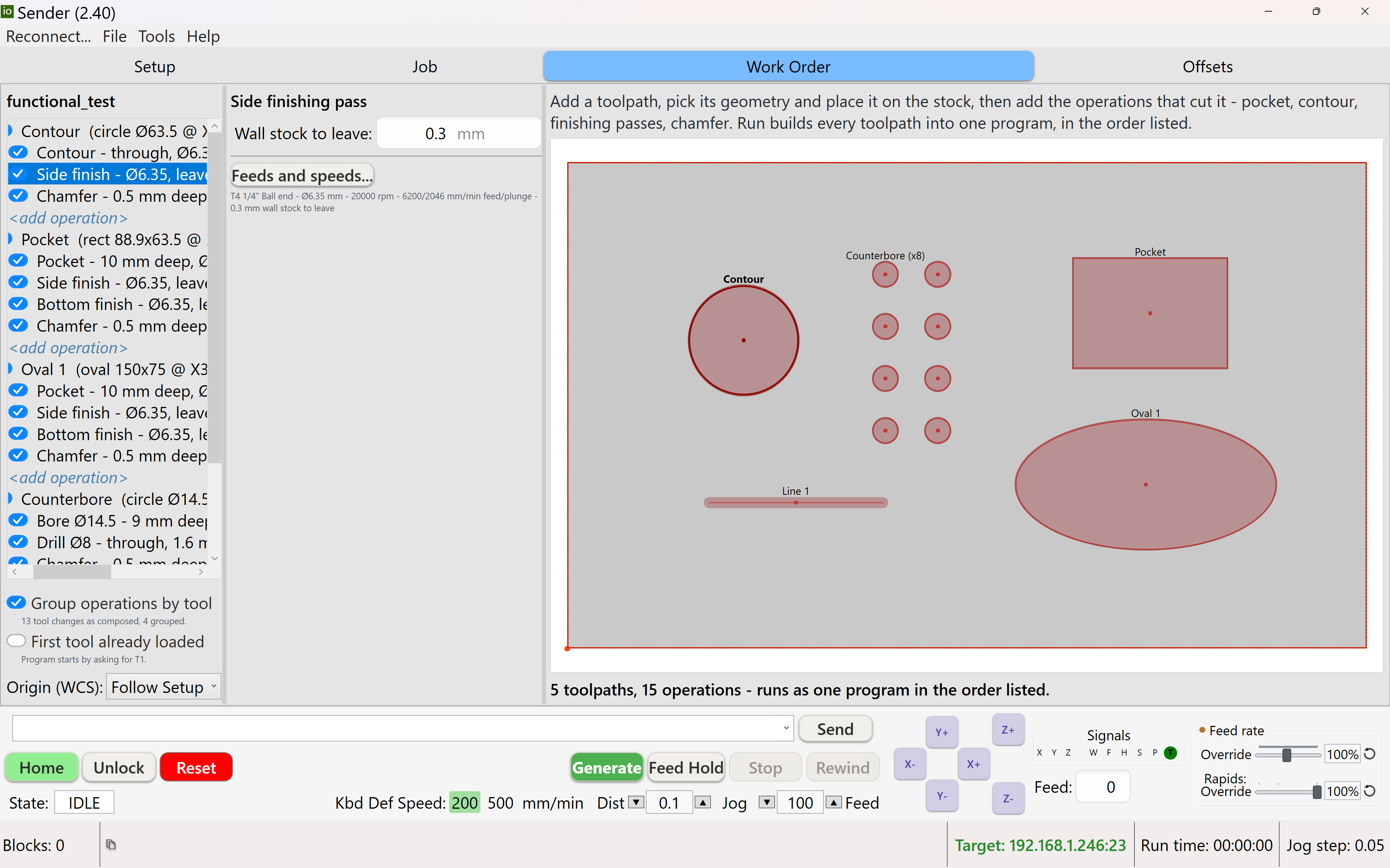
What you're looking at:
- Toolpaths — the geometry. Nine kinds: Line, Circle, Oval, Square, Rectangle, Surface (face a whole area), Text (engrave or V-carve with a V-bit), SVG artwork (engrave or V-carve a logo) and Indirect (repeat another toolpath, or a whole group of them, somewhere else). Text and SVG artwork have a page of their own — see Engraving & carving. Add one, then hang operations underneath it: Pocket, Contour, Drill, Bore, Side finish, Bottom finish, Chamfer, Countersink, Surface, Engrave, Clear floor (an end mill flattens the floor a V-carve leaves) and Mark (a V-bit traces the outline as a shallow groove). Geometry belongs to the toolpath; the operations act on it — that's why a counterbore is just one circle carrying a shallow bore, a through drill and a chamfer on the same centreline, rather than a special case. Which operations are offered depends on the geometry: only a V-carving toolpath is offered Clear floor, only a shape with corners is offered corner reliefs.
- Enable checkboxes per row — untick a toolpath or operation to leave it out of the next Generate; ticking/unticking a toolpath cascades to its operations, and back.
- Feeds and speeds — a dialog proposes chipload-based feed/speed/depth-of-cut numbers per tool and the Material picked in Setup's Stock group, and remembers what you actually used last. Each operation also has a per-row Climb/Conventional cut direction (defaulting to Conventional) — climb orbits the same direction as the spindle for an internal feature (a bore/pocket) but the opposite direction for an external one (a contour cutting a part free), and ioSender works out the correct raw winding for you rather than you having to reason about CW/CCW by hand.
- Generate — compiles every enabled row into one g-code program, not a pile of separate files. Tool order is chosen, not stumbled into: each candidate ordering is scored by simulating it to completion, so a job with many sections and only a few distinct tools still does the minimum number of real tool changes — the compiler tracks what's already in the spindle rather than revisiting a tool because of where it happened to sit in the tree.
- Run — sends the generated program to the Job tab as the actual loaded job (see below), then streams it through the normal run pipeline.
What Generate tells you
A Generate on a large work order can take a while, so it says what it is doing and what the result will cost. "Compiling work order…" while it works, then a line naming the work order and the outcome: "Work order compiled — 4,777 lines in 9.6 s, est. run 12m 40s." That estimate is the difference between a four-minute engraving and a forty-minute one, known before you press Run. It is a naive kinematic estimate with no acceleration model, so it reads optimistic — many short moves will take longer than it says. For the same figure broken down per toolpath, look at the toolpath outline in the Job tab: every section header carries its own estimate.
When Generate is disabled, the reason is on the button — the tab's own explanation, in words, not a generic "nothing to run yet". A tab that blocks generation always knows exactly why; that reason used to go only into a warnings panel you might have scrolled past, so the button simply did nothing and explained nothing.
The blank a work order was authored for
A work order is a recipe for a known piece of stock — you feed it a blank of a given size and run it — so the blank's size is recorded in the work order file rather than borrowed from whatever Setup happens to be showing. That is what the layout diagram draws against, which is why a work order opened months later still looks right.
A work order saved before this existed has no blank recorded, and is shown as unknown rather than quietly falling back to Setup's current numbers. That is deliberate: a drawing of the right toolpaths on the wrong stock is a drawing that lies. Enter the size once and it is kept with the file. Material is not stored per work order — that stays one shared value on Setup, because two authorities over it is how they drift apart.
A V-carve now cuts fewer, heavier passes. Depth of cut drives the carve step, where it used to sub-divide far more finely — a groove that took six passes may now take two. The reason is geometric: consecutive carve passes tile the cone exactly, so the fine detail added by one pass was being removed by the next. Run the first one and watch it, especially in a hard material.
A Bore's emitted feed may differ. Where a bore follows a wall, the engaged edge of the cutter travels a bigger circle than the tool centre the feed rate governs, so it was running faster than asked; those passes are now compensated by the ratio between the two circles. A full-immersion helix is not compensated, because there the assumption does not hold.
Running a Work Order
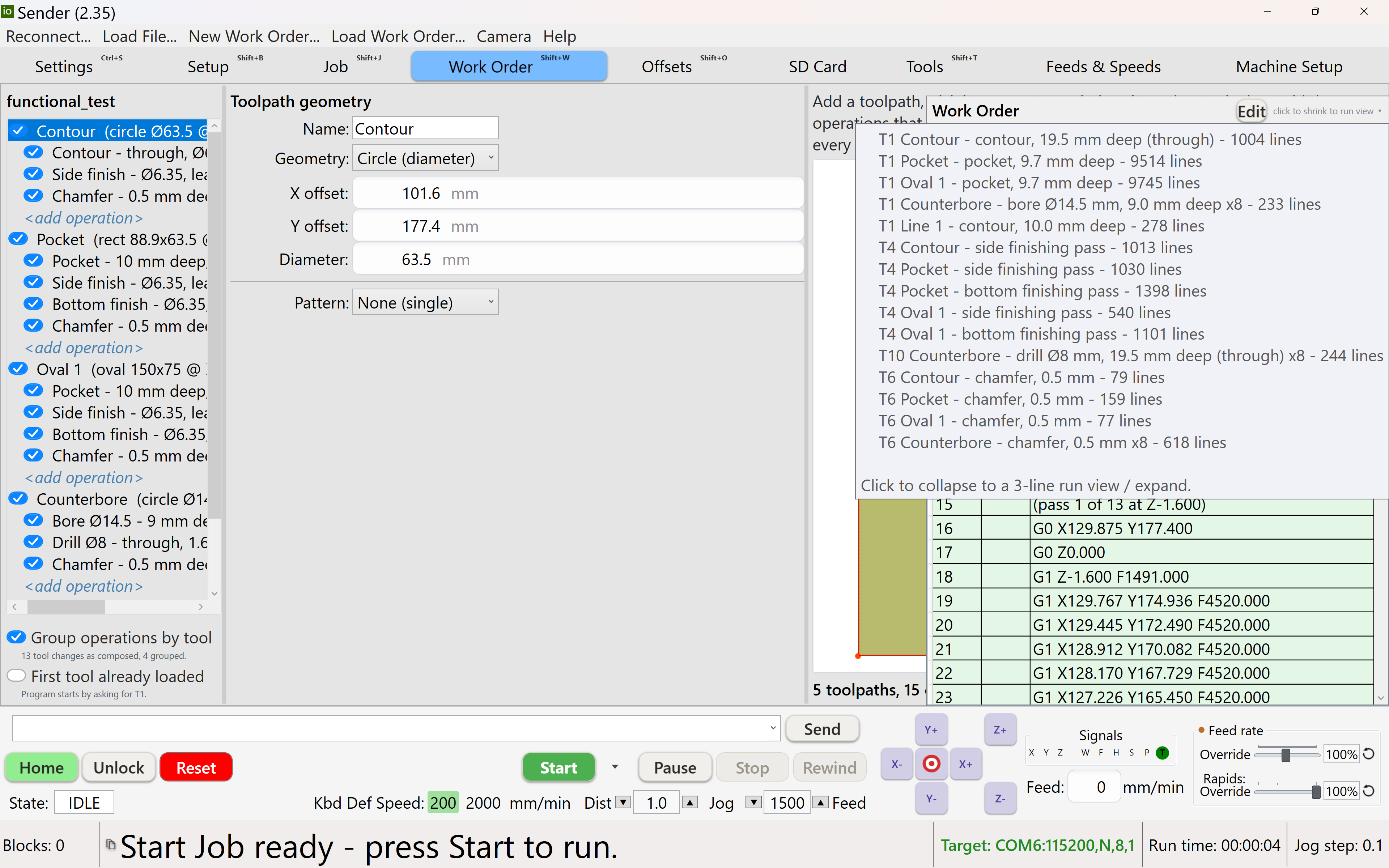
Pressing Run switches you to the Job tab and loads the generated
program into its real, docked program list — the same list a loaded .nc file uses, not a
separate floating preview, with the same live per-line status (ok/*) as any
other run. When the run ends — completes, is stopped, or a prerequisite check fails — ioSender switches
you back to Work Order and restores whatever program was loaded before the run, so re-running the Work
Order never clobbers a file you had open.
A generated work order gets a toolpath outline like any other program: the Job tab's list groups it by tool change, one collapsible section per tool, each with its own estimated run time. That is the quickest read on what Generate actually produced — and it is also how you re-run a single toolpath afterwards without regenerating anything.
Mark only — dimple the hole centres and cut nothing else
Some holes are better drilled somewhere else. A router that flexes will not drill aluminium properly, so the job splits in two: the machine marks where the holes go, the marks are deepened with a punch, and the holes themselves are drilled on a pillar or mag drill. Mark only — a checkbox beside Group operations by tool — is that first half. Generate then emits a program that puts a shallow dimple at the centre of every Drill and Bore in the work order and cuts nothing else.
It is a property of the run, not of the work order's content. Nothing you authored is changed or stripped: every drill keeps its real diameter and depth, because the work order is still the document that says what gets drilled at each dimple. Only the generated program is reduced.
- One dimple per toolpath, not per operation. A toolpath carrying both a Drill and a Bore describes one hole and is punched once. A pattern on the toolpath comes across intact, so a 3 × 2 grid still yields six dimples — and an Indirect toolpath's borrowed holes are marked along with the rest.
- A Bore counts as a hole. It is milled rather than drilled, but its centre is exactly as much a place you are about to put a drill.
- Everything else is left out — that is the point, not a side effect. A work order with no enabled Drill or Bore would reduce to an empty program, so it is refused before Generate rather than emitting a file that parks and does nothing.
- The dimple has its own tool and feeds. The Feeds and Speeds… button that appears under the checkbox opens the same dialog every other operation uses — tool, diameter, depth, spindle speed, plunge, with the same recommendations. The diameter there is the dimple's, not the bit's. It defaults to a 3.175 mm (1/8") dimple 1.4 mm deep, and it is never pecked: one plunge is the whole thing.
- The bit has to come to a point. A twist drill, a V-bit or a countersink will do; an end mill leaves a flat bottom a punch cannot find, and you are told so rather than left to discover it on the part.
- Read the summary line against the part in front of you. It states what will actually be emitted — "9 hole centres: 1/8" drill at Ø3.175 mm x 1.4 mm deep, 8000 RPM, plunge 400. Every other operation is left out." If that count doesn't match the holes you can see, something is disabled that you meant to keep.
Mark a part in the morning, reopen the work order in the afternoon and press Generate, and you get dimples again — the tick is remembered like every other field. Two things tell you, and it is worth knowing both, because this is a program that looks like the job and is not: the summary under the checkbox while you are in the tab, and the generated program's own first lines, which say *** MARK ONLY with the hole count, the dimple depth and the bit, followed by "The holes are NOT drilled here, and every other operation is left out." Those travel with a saved program, so a
.macro found next week can still be told apart from the real job.Surfacing the spoilboard
Flattening the spoilboard is a Surface toolpath like any other operation — same tool list, same feeds & speeds advisor, same generate/run path, same dry run. Tick Entire Spoilboard and it covers the whole bed.
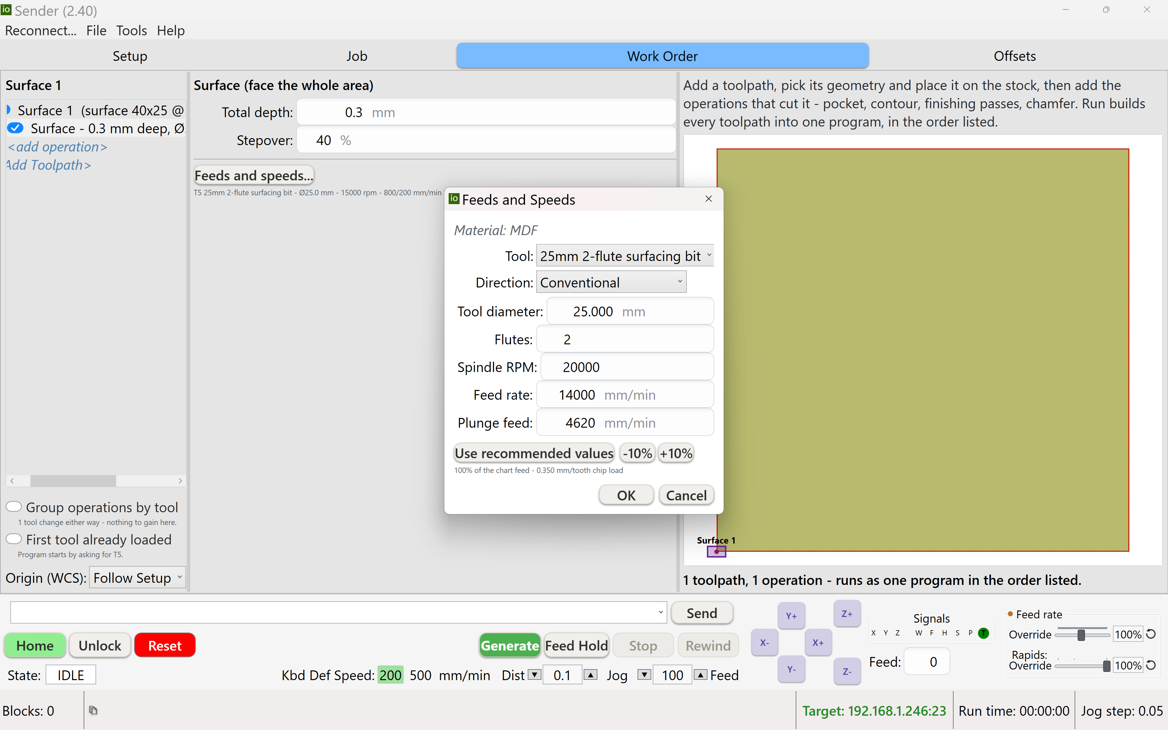
By default it deliberately does not trust the work order's coordinate system: it touches off its own fresh Z0 and works in machine coordinates, because the whole point of resurfacing is that the board is not where you last thought it was. It borrows a scratch WCS slot and restores it afterwards, so establishing that temporary origin never steps on your real one.
There is one case where that is actively wrong, and a checkbox for it: Use the work origin already set, nested under Entire spoilboard and only available while that is ticked. After a Full work surface height-map run, Z0 is the highest of sixteen probed points — and the self-touch-off would throw that away and replace it with one eyeballed touch at one spot, which cannot tell you whether you touched a high spot or a low one. Off by default; tick it when an origin you trust more already exists.
Both this and the height map's Full work surface used to take the machine's travel limits (
$130/$131) as the extent of the board. That is only true where the board
fills the table — on a machine with the toolsetter mounted off the front edge, the last stretch of Y
travel is air, and a raster across it runs the cutter through nothing at best. If your board is smaller
than your travel, describe it in Machine Setup step 3's
Work surface (spoilboard) section and both features read it. Leave it undefined and
they assume the board fills the table, exactly as before.Which coordinate system it runs in
A work order carries its own WCS field. Leave it on Follow Setup and
it resolves live at Generate time to whatever Setup is currently targeting; or pin it
to a specific G54–G59 if this job always belongs to one fixture. Pinning matters
because Setup is shared with a plain loaded file — its live selection isn't something a work order saved
weeks ago can treat as a stable reference.
Repeating a toolpath elsewhere — Indirect and groups
A toolpath with Geometry: Indirect is not a shape at all. It carries no dimensions and no operations of its own: it borrows both, live, from another toolpath you name as its source, and supplies only a different position to run them at. That is the difference between it and Duplicate, which forks an independent copy — change the original's diameter or add a chamfer to it, and every Indirect copy picks the change up at the next Generate. A duplicate does not.
- Absolute or Relative. An Indirect toolpath's position can be an ordinary coordinate, or an offset from its source. Relative is the one to reach for when the pair belongs together — move the original and the copy follows it, still 120 mm to the right.
- Group a set, then copy the set. Give several toolpaths the same Group label and the tree collects them under one header you can enable or disable together. An Indirect toolpath can then point at the group rather than at one toolpath, and it copies the whole arrangement — rigidly, so the members keep their spacing. The payoff is the part worth planning around: add a toolpath to the group and it appears in every copy.
- Hold a member back per copy. Each Indirect copy can skip individual members of the group it borrows, which is how you cut the full set in one place and all-but-one somewhere else. The anchor stays the anchor either way, so holding a member back never slides the rest sideways.
- Only real toolpaths carry a group, and an Indirect one cannot point at another Indirect. Between them those two rules make a circular reference impossible to build rather than something to be warned about.
- A pattern belongs to the source: a group of patterned toolpaths copies as a group of patterned toolpaths, and the Indirect toolpath has no pattern of its own to multiply it by. A broken reference — a source renamed or deleted — is reported in the tree rather than quietly cutting nothing.
Corner reliefs (dogbones)
A round cutter cannot leave a square inside corner, so a square part will not seat in the pocket cut for it — the corner keeps a radius the part's corner has to go into. Corner reliefs, a checkbox on Square and Rectangle toolpaths, fixes that the way a joiner does: at each corner the cutter pokes out along the diagonal until its circle passes through the true corner point, clearing exactly the material a square peg needs.
- It is opt-in because it leaves a mark. Each relief overcuts both walls by a little under a third of the cutter's radius — a small round nick in the corner. That is the trade: a part that seats, against two visible nicks per corner.
- Only inside corners are relieved. The reliefs are cut by the passes that run internal walls — Pocket and Side finish. A Contour ignores the setting entirely, because its corners are convex and a round cutter already reproduces them exactly.
- The relief is sized by the cutter that cuts it, not by the toolpath, so the same rectangle roughed with a 1/4" and finished with a 1/8" gets the right relief in each pass rather than one compromise.
Save Drawing — the work order as a shop drawing
Right-click the stock diagram and choose Save Drawing… to write the whole work order as a dimensioned PDF: a drawing of the blank with every feature on it, and a feature schedule underneath keyed to it. This is what makes a work order portable — to a second machine, to a manual drill, or to somebody else's bench.
- Balloons key the drawing to the table. Each feature gets a lettered, colour-matched balloon, and the table lists its geometry, position, quantity, operations and tooling. The drawing itself carries only the dimensions with nowhere else to live — overall stock size, the keep-out margin, the origin — because forty leader lines fighting each other is worse than a hole chart.
- Every instance of a pattern is listed with its own X and Y, not just a count. A "Qty 6" tells the person at the other machine that a pattern exists and leaves them reconstructing six positions from a pitch and a corner, by hand, next to a running spindle. The numbers are already known, so they are printed.
- It is a drawing of the work order, not of your screen. The selection highlight is left off, and a held-back toolpath is printed dimmed and labelled rather than omitted — its balloon keeps its letter and colour, because a key that changes is not a key.
- It needs a stock size, and at least one toolpath; without them the menu entry is disabled rather than producing a sheet that dimensions a placeholder. Long feature schedules spill onto further pages and the drawing keeps page one to itself — the drawing is the part that goes to the machine, so it is not the part that gets shrunk.
Your own tools
The tool list isn't fixed. Add your own cutters alongside the built-ins from the Feeds & Speeds dialog's tool editor — an added tool behaves identically to a built-in one, including in the advisor and the tool-ordering pass. Operations record the tool by name, so a saved work order stays readable, and reconciles itself on load if the list has changed underneath it rather than silently binding to the wrong cutter.
Work Order doesn't have its own separate stock-setup step. It uses the same Setup tab and cached origin/tool-length reference as everything else. Generate asks once — proceed on the currently cached Setup? — rather than gating the tab behind a certified "Setup complete" state.
Tool numbers are preassigned from the Feeds & Speeds tool list position. If your machine's ATC macros reserve a tool number for a fixed sentinel (for example, a 3D probe already fitted to the spindle), that number is skipped in the Work Order's own numbering — check your macro setup before assuming T-numbers line up 1:1 with the tool list.
Running a work order in Dry Run neutralizes the spindle, the same as dry-running a loaded file. (It didn't always — a work order used to bypass that and could fire the spindle for real.)
Engraving & carving #
Two of a Work Order's toolpath geometries put a shape into the surface rather than cutting a part out of it: Text and SVG artwork. Both hang the same Engrave operation underneath them, and underneath that they are the same engine — it takes closed outlines and has never known whether a letter or a logo produced them. So everything on this page about depth, bits and passes applies equally to a word and to a badge.
A Text or SVG artwork toolpath offers Engrave, and Clear floor beside it once there's a floor to clear. There is deliberately no Contour, Pocket or Chamfer: those trace or clear a shape, and "the outline of the logo" is not a path that describes the logo. If you want a border cut around artwork, that's an ordinary Circle or Rectangle toolpath sitting next to it.
Everything here cuts with a V-bit in the spindle, on the machine Setup and Work Order already describe. It is unrelated to burning an SVG on a diode laser, which is a separate path with its own dialog and its own emitter.
The two ways a letter gets cut
Pick a toolpath with Geometry: Text, type into the Text box (Enter gives you a second line), and the Font dropdown decides which of these you get. It is the single most consequential choice on the panel:
| Font choice | What the bit does | Best for |
|---|---|---|
| (single stroke - engrave) | Each letter is drawn as one pass down its centre line — a pen line, not an outline to be cleared. The depth comes from the Stroke width you ask for on the Engrave operation, plus the bit's angle. | Small lettering, serial numbers, anything where the letter is barely wider than the bit. The geometry is generated, so it doesn't depend on a font being installed. |
| Any installed font | V-carves the real glyph outline: the bit rides the outline at a depth set by the local stroke width, so strokes widen and narrow and the corners come to a point, the way the typeface actually draws. | Larger lettering, signs, anything where you want the carved look. Bold and Italic tick beside the dropdown. |
Cap height is the size you actually mean by "10 mm lettering" — the height of a capital. Round letters overshoot it a hair, as they should. Lowercase is engraved as uppercase, and a character the font cannot draw is skipped rather than cut as a gap.
Text fitted inside a shape
Text doesn't have to be its own toolpath. Any Line, Circle, Oval, Square or Rectangle carries a Text checkbox: tick it and the same Text/Cap height/Font fields appear, and an Engrave operation is added that cuts the lettering inside the shape. The shape still cuts exactly as it did — this is an addition to it, not a replacement.
- Leave Cap height at 0 and the text is auto-sized to the largest that fits. Give it an explicit size that doesn't fit and the job is refused at Generate rather than cut small — and refused by the same resolver the compiler uses, so a refusal and a cut can never disagree about what would have fitted.
- A Line is a baseline. The text runs along it at its angle; Vertical align decides whether it sits on the line (Top), hangs below it (Bottom) or straddles it (Center), and Horizontal align distributes it along the length.
- Curved shapes fit against the curve, not against a bounding box, and are centre-only — sliding a block of text around inside a circle would void the fit guarantee.
- The stock preview draws the fitted text live, at its real size and placement, as you type.
SVG artwork
Choose Geometry: SVG artwork, browse to a .svg, and set Artwork
width. It carves exactly the way lettering does — same depth field, same passes, same stock
placement, same preview. Angle rotates it about its anchor, and the Engrave operation is
added for you, since it's the only one that applies.
- Width measures the ink, not the page. Padding around a logo in the source file doesn't count, so the number you type is the number you get on the wood. The height follows from the artwork's own proportions.
- The file is referenced, not copied into the work order. Re-export the logo over the same filename and the next Generate picks it up. A file that has moved or been renamed is reported at Generate rather than quietly cutting something stale.
- The size readout answers the real question while you're still choosing — "Artwork is 3.81:1. At 150 mm wide it cuts 150.0 x 39.3 mm, 42 outlines." — rather than at Generate, when you have already committed.
- Artwork it cannot fully read is refused, with the reason named, both in the editor and again at Generate. That is deliberate and it is the important behaviour here: silently cutting the half it understood gives you a preview that looks plausible and a missing piece you don't discover until it is missing from the work.
Negative — the artwork standing proud
A V-carve normally cuts the logo into the wood. Tick Negative and it does the opposite: everything around the artwork is carved away and the logo is left standing at the original surface, the way a raised-letter sign is made. Panel decides what bounds the recessed area:
| Panel | What it carves | Needs |
|---|---|---|
| Rectangle | A frame the Border distance outside the artwork's ink on every side (5 mm by default). The readout states the resulting panel size, because that — not the ink — is what has to fit your stock. | Nothing. Works on any artwork. |
| Artwork outline | The artwork's own enclosing outline — a badge's border circle, say. Inside it floors, the rim stands at the surface, the art stands proud, and the corners outside the circle are never touched. No Border is needed, so the field hides. | Artwork with a single outline enclosing everything else. The editor's readout tells you whether the file you picked has one; if it hasn't, Generate refuses by name rather than quietly substituting a rectangle. |
The panel floor is whatever Max carve depth says on the Engrave operation. Leave that at 0 and the background is carved as deep as the bit physically can, which on a narrow V-bit is a great deal deeper than you want. Set a cap before running a negative.
Depth — the part that surprises people
A V-carve has no depth setting, and that is not an omission. Depth is a consequence: at every point the bit descends until its cone exactly fills the local width of the shape. A hairline stroke is shallow, a thick one is deep, and that is what produces the carved look. Two fields sit on top of that:
| Field | What it does |
|---|---|
| Max carve depth | A ceiling. 0 = automatic — the deepest the bit itself can reach. Because depth follows width, a cap cannot touch anything already shallower than it: fine detail comes out byte-identical and only the areas wide enough to want more flatten off. This is what makes a very sharp bit usable on artwork that mixes hairlines with thick strokes — a 15° bit cuts a 0.5 mm stroke crisply where a 60° bit mushes it, but left uncapped it would drive the widest feature ten millimetres into the stock. The bit's own limit stays a hard ceiling: a cap can lower it, never raise it, and a request that had to be limited says so. |
| Stroke width | Single-stroke engraving only. How wide you want the engraved line to be — width is what you can measure on the finished part. The plunge depth is worked back from it and the bit's included angle, which is why the same 0.8 mm line is 0.40 mm deep on a 90° bit and 0.69 mm on a 60° one. |
On a carve, the operation's Depth of cut is the axial step between depth levels — the shallower levels are not geometry, they are just stepping down. Consecutive passes tile the cone exactly, so a bigger step means fewer, heavier passes and the same finished shape, not a shallower carve. Set it to the carve's full depth to cut each groove in one, if the bit will take it. If you have work orders saved from before this field drove the carve, they'll generate noticeably fewer passes now — worth watching the first one, particularly on a fine-tipped bit.
Clearing the floor
Where a carved area is wider than the cone can span, the V-bit floors it with rings of its own tip, and the walls of adjacent rings meet in a ridge half a depth-step tall. The walls and the standing artwork come out crisp; the floor is corrugated. Clear floor is a second operation on the same toolpath — offered only where the toolpath actually V-carves — that sends an end mill over that floor to flatten it.
- Its depth is not a setting. The floor depth and the cone angle are read from the sibling Engrave operation's V-bit and cap every time, so the mill's floor and the V-bit's floor are one number by construction. Remove the Engrave, or give it a tool that isn't a V-bit, and you're told by name rather than given a guess.
- Not offered on a single-stroke engrave, because there is no floor: a stroke font cuts a pen line down each letter's centre, never a region wide enough for the cone to bottom out in. If Clear floor isn't in the list, check the Font — that's usually why.
- Below carve floor (0.1 mm by default) is the one number you do set, and it matters: at exactly the carve's depth the mill's end face rides a surface the V-bit already finished, removes nothing but ridge tops, and rubs — which burns hardwood. A tenth deeper keeps it taking a continuous chip, and the step it leaves at the wall is invisible.
- Use a flat-bottomed end mill. A ball nose is the one profile that cannot flatten a floor — it leaves a field of scallops — and is refused.
- Anything narrower than the mill plus two wall toes stays the V-bit's work, so the two operations divide the floor between them. The order is yours: run Clear floor before the Engrave and the mill pockets solid wood, so it cannot rub at all.
Marking a line
Mark is the other V-bit operation, and it is offered on the plain shape geometries rather than on artwork: the bit's tip rides the nominal outline with no cutter offset, leaving a shallow groove — a stamp boundary, a fold line, a cut-here line. Unlike Contour it doesn't offset by a radius or cut to a total depth; you set the groove's width and the depth follows from that and the bit's angle, exactly as a stroke engrave does. A Mark is always one pass. Tick Dashed and it becomes a dash-and-gap line: on a closed shape the pitch is nudged so a whole number of dashes goes round and the pattern meets itself with no stub.
A V-carve is the most expensive thing Generate does — the depth field behind it is genuinely computational. Generate says it is compiling and reports how long it took, and the result is cached, so returning to a job doesn't pay for it twice. Changing anything that affects the cut — the artwork, its width, the bit, the cap, the step — invalidates that cache correctly, so you never have to wonder whether what you're looking at is stale.
Burning an SVG on a diode laser #
A diode laser engraver is a different machine from the router the rest of this manual describes, and
ioSender treats it as one. File → Load SVG Laser Job… takes a
.svg, asks how big, how hard and where, and hands the resulting program to the
Job screen like any other file. It is not a Work Order
toolpath and it is not the V-carving on the Engraving & carving page: those
emit grblHAL — bracket expressions, tool changes, tool-length offsets, a Z depth per pass —
and a laser controller is usually plain Grbl, which rejects all of it. The two paths share only the
geometry reader, so the same logo file works on either.
The menu entry is hidden by default and appears only when ioSender is started with
-enableSVGLaserJob on its command line (case doesn't matter). That is per launch, not a
remembered setting: no flag, no entry — and nothing in Settings →
Keyboard to bind either, so the whole feature is genuinely absent rather than merely out of sight.
It is held back because a laser job that reaches the material with the wrong exposure spends the
material, and the path is still earning its time on real machines.What the machine has to have
$32=1— laser mode. With it on, Grbl blanks the beam during a rapid by itself and scales power with speed, which is what stops corners burning dark as the head decelerates into them. The dialog reads$32and says so in the pinned note at the bottom; with laser mode off it warns you, and writes the warning into the program's header as well. Rapids are emitted withS0regardless, so a file is not relying on a setting being right.$30— the full-power S value. An S word means nothing on its own: S150 is a light mark against a$30of 1000 and full power against a$30of 255. The dialog reads it live and shows every power as a percentage of it.- No homing needed. These machines usually don't have it, so there is no work coordinate system to set. The head's position when the job starts becomes 0,0 — you jog to the corner of the material and burn from there.
Most diode engravers park at the back-left corner and their whole table lies at negative Y: the work is in front of the origin. An ordinary router is the mirror of that. The Origin is the back-left corner tick on the Artwork tab is where you state which you have, and the dialog then spells the instruction out in the pinned note — jog to the artwork's TOP-left corner for a back-left machine, LOWER-left for a front-left one. Get it backwards and the job runs off the back edge into the stop, which on a machine with soft and hard limits both switched off is a stalled axis, not an error message.
The dialog, tab by tab
Pick the file and the SVG to laser dialog opens. Its three tabs are the three separate questions; the note pinned underneath them is always visible, because that is where the things that spoil material are said.
| Tab | Decides |
|---|---|
| Artwork | How big the art is, and where on the table it goes. |
| Copies | How many of it, how far apart — and the power ramp that turns those copies into a test strip. |
| Burn | Power, feed, passes, shading, and the machine's squareness correction. |
Everything except the beam switch and the file name is remembered between jobs. Power and feed for a material are found by burning test strips, and re-deriving them every session is how a good setting gets lost.
Artwork — size and placement
- Width measures the ink, not the page. The artwork is normalised to its own outline, so padding in the source file counts for nothing and the number you type is the number you get on the material. The line under the field states the height that implies.
- Origin X / Origin Y move the whole job in from the parked corner. Leave them at zero and the artwork starts exactly where the head is standing — fine for a bench job you jog to, useless for a fixture, where the work sits in a known place and the file has to reach it. This is also the only way to move the art: adding whitespace to the SVG does nothing, because nothing was drawn in it.
- The readout on the Copies tab states the whole rectangle every copy occupies, in X and Y. That is the number to check against your travel — a modest pitch can still add up to a reach that does not fit.
Press OK and the placement is checked before anything is emitted: X behind the stop, Y on the wrong side of the origin for the anchor you chose, or a reach past the travel the controller reports. A refusal puts you back in the dialog with your numbers intact. The travel test only runs when the machine has actually told ioSender what its travel is; an envelope is never invented. This is a refusal rather than a warning for one reason: on a machine with
$20=0 and
$21=0 — soft limits and hard limits both off, which is the usual state of these
engravers — nothing below this point will catch the move. The gantry simply drives into the
stop.One slip gets an offer instead of a refusal: a Pitch Y signed the wrong way, which steps the copies away from the table. The dialog names the value it thinks you meant and asks. It is not applied silently — if you really did mean +Y, the job would otherwise run and quietly not be the one you pictured.
Copies — and the test strip
Copies repeats the same artwork across a fixture, each one a Pitch X / Pitch Y further on than the last. Doing it here rather than by duplicating the art in the SVG keeps one drawing as the single source of the shape: change the logo once and every copy changes. Pitch is signed, and on a back-left origin the table lies at negative Y, so stacking copies front-to-back needs a negative Pitch Y.
Underneath that is the feature worth knowing about even if you only ever burn one part:
- Power step adds an S value to each copy after the first. 50 with a power of 200 gives 200, 250, 300… — the same artwork at rising exposure, in one job, on one piece of material, same focus, same session. Negative ramps down. Fill step does the same for the shading power, independently.
- The readout states what the ramp actually produces, first copy to last, and says
CLAMPED if it runs past
$30. That matters: power cannot exceed full, so an overshooting ramp burns two or more copies at the same power while the file claims they differ, and a test strip that silently compares a value against itself is worse than no test strip. - Leave both steps at 0 and every copy burns identically.
Burn — exposure, passes and shading
| Field | What it does |
|---|---|
| Enable beam | Untick it for a dry run: the head follows the entire path at the same feeds, every S word is 0 and the laser is never enabled, so you can watch where the job lands before spending material. Not remembered — it comes back ticked on every import, because a "no burn" that survived into a later session shows up as a job that ran perfectly and marked nothing. The state is stated in the pinned note and written into the program header. |
| Power (S) and Feed | Shown as a percentage of
$30, and combined into the number that actually matters: exposure, power
divided by feed — how much beam energy lands per millimetre travelled. That, not the S value on
its own, is what decides whether wood browns or chars. |
| Travel | Feed for the rapids between outlines. Beam off. |
| Passes | How many times each outline is traced. Several light passes generally beat one hot one — less charring, and less chance of the beam wandering out of focus as the surface chars away from it. |
| M4 dynamic power | On (and with $32=1) power scales with
speed, so corners are not burned dark as the machine decelerates into them. Untick for
M3 constant power, which suits cutting through more than engraving. |
Shading — Fill enclosed areas — scans back and forth across the inside of each shape instead of only tracing its boundary. Holes and counters are left unburned: the gap inside a ring, the middle of an o. It has its own power and feed, because shading covers area where an outline draws edges, and its own Interval — the spacing between scan lines, around the beam's spot size. 0.1 mm suits a typical diode; tighter overlaps and darkens, wider leaves visible banding. Trace outline after shading lays the boundary on top at the end so the edge comes out crisp.
- The readout compares the shading's burn with the outline's, which the two pairs of numbers on their own hide: an outline at S150/F1200 and a fill at S400/F3000 look like a large power increase and are in fact the same burn.
- Depth of a fill is set by the interval as much as by the power. A fill is a raster of lines a fixed distance apart, so halving the interval puts twice the energy into the same square millimetre while every number on the tab stays where it was. The readout therefore leads with an areal figure, power ÷ (feed × interval), and names the interval in the same breath. Treat it as relative, never as a prediction — a fill at S600/F800 with a 0.1 mm interval took nearly 7 mm out of cedar.
- Shading is slow, and it tells you before you start rather than forty minutes in: the estimate states the number of scan lines and an upper bound in minutes. It assumes every line crosses the full width, so the real time is shorter.
Squareness — correcting a racked gantry in software
A lightweight engraver's gantry can sit slightly racked, carrying the head a little forward as it travels in X, so a commanded square burns as a parallelogram. Where the frame cannot be squared mechanically — and on a belt-driven machine it may not hold — the Burn tab compensates for it. You do not type a coefficient; you type three numbers you measured off a burned test square:
- D1 — the diagonal from the parked home corner to the far corner.
- D2 — the other diagonal.
- Side — the square's side.
The shear follows from (D1² − D2²) / (4 × Side²) and the
readout states it both as a coefficient and as the correction it amounts to at the far side of the bed.
Only the difference of the diagonals matters, so a ruler that reads both a few millimetres short
— as one does against a charred corner — cancels out. Zero any one of the three and
compensation is off.
Burn a square, measure both diagonals and a side, type them in, burn another. A frame that gets moved, re-tensioned or carried outside loses its set — re-measure rather than trusting a stored figure. Equal diagonals mean no correction, which is what you are aiming at.
What it writes, and the one thing to know about aborting
The program that lands on the Job screen is deliberately readable. Exposure is emitted as named constants at the top — a power and a feed, plus a second pair when shading is on — and the placement as two more, so retuning the job is editing a handful of numbers rather than hundreds of cut moves — and a per-copy power ramp is just the same constant re-declared part way down. Everything below the header is the artwork's own geometry from 0,0: the placement is applied once, by the rapid that moves in to it. Where the controller does not support expressions the constants are substituted as the file loads, so what reaches the wire is always literal S and F words. Saving the program keeps the constants rather than the substituted literals.
The header is written for the day the file is opened again without the dialog: artwork size and outline
count, power against $30, feeds, M3 or M4, the placement, which corner the anchor means,
whether the beam was disabled, and a $32 warning if one applied.
Because there is no homing and no work coordinate system, the job labels the parked corner as 0,0 with G92 and clears it with G92.1 on its last line. Stop the job part way and that clear never runs, so the temporary origin stays applied and the next job starts from the wrong place. Send G92.1 from the MDI after any abort. The program says so in its own comments too.
When it refuses the artwork
Each of these is a refusal with the reason named, before anything is emitted — a partial logo looks like a successful job right up until you notice a piece missing, by which point the material is spent.
- Nothing measurable — the file has no drawable outlines.
- Unreadable — the importer says what it could not parse.
- No closed outlines — it read the file and there is nothing to trace.
- Elements it cannot handle — this one asks rather than refuses, listing what will be missing, and defaults to No. What it can read will burn; the rest is simply absent.
Height Map — cutting a surface that isn't flat #
Nothing is flat. A spoilboard dishes, a sheet of plywood bows, a workpiece clamped at its corners lifts in the middle — and a cut that is only a few tenths deep simply disappears where the surface falls away, then bites where it rises. Tools → Height Map probes a grid over the area, builds a surface from what it finds, and then rewrites the loaded program to follow it: every Z in the job is shifted by the local height, so a 0.3 mm engrave stays 0.3 mm deep everywhere.
It is also how you resurface a spoilboard, which is a different job with a different shape — and that is the first choice on the panel.
The two modes
| Area to probe | What it is for | What it needs first |
|---|---|---|
| From program | Compensating a job. It probes the loaded program's footprint, in the current work coordinates, so the map lines up with the job you are about to cut. Set from program limits fills the area from the loaded file; X/Y/W/H are editable afterwards. | A work origin already set on the stock — see Setup — and, for Apply, a loaded program. |
| Full work surface | Resurfacing the spoilboard. It maps the whole board and sets the work origin itself. | Nothing. No Setup pass, no corner to probe. X0 Y0 is placed at the board's corner before probing and Z0 on the highest point found once it finishes. |
The panel changes with the mode, which is deliberate: From program gives you an area and a grid size in millimetres (with a Lock to keep X and Y equal), while Full work surface gives you divisions per axis instead and tells you how many probes that is. A gently dished board needs far less than people expect — 4 × 4 is sixteen points and usually plenty.
Full work surface takes its extent from the Work surface (spoilboard) section of Machine Setup step 3. Leave that undefined and it assumes the board fills the table — which on a machine with the toolsetter mounted off the front edge means probing thin air at one end. The same field feeds Work Order's Entire spoilboard.
The probe, and the numbers that are not on this panel
The Probe dropdown picks which of your probes does the work, and that probe's own search distance and approach feed come from its definition in Machine Setup step 5 rather than being retyped here — which is why this panel has no depth or feed field. The search distance has to cover how much the surface actually varies. With no probe defined at all the panel says so, instead of offering a Start that cannot work.
Two controls on the panel are about how the head moves between points:
- Hold at each point (move the touch plate). A spoilboard will not close a circuit, so on anything non-conductive the plate has to travel with the probe. Ticked, the machine positions over each point and waits: put the plate under the bit and press Continue (Cycle Start does the same). It holds before every point except the first, where you are already standing at the machine. Untick it only where the probe reaches the surface on its own.
- Drop allowance. Between points the tool lifts clear of the surface and then searches that lift plus this allowance, so a point up to the allowance lower than the one before it is still found. The note under the field spells out all three distances in millimetres as you change it. Raise it for a board that steps or dishes sharply; the cost is a longer search at every point.
Running it
The right-hand pane follows the run rather than making you choose a view: Steps while you are setting up (and the steps themselves change with the mode), Program when you press Start — the actual probing program, listed before anything moves, rebuilt on every Start — and Surface Map when the run finishes.
| Button | What it does |
|---|---|
| Start | Probes the grid a point at a time. The blue button is always the one to press next, so it moves to Continue while the run is holding for you. |
| Continue | Releases a hold — you have moved the plate. Cycle Start is the same thing. |
| Retry | Clears the alarm and carries on from the point that failed, keeping every reading already taken. See the warning below for when it is not offered. |
| Stop | Cancels the run in progress. What was gathered is kept, so a Retry can still pick it up. |
| Apply | Rewrites the loaded program to follow the probed surface. It needs a program loaded; with none it says so rather than doing nothing. |
| Save / Load | Stores the map as a .map file
and reads one back, so a board you mapped last week does not have to be probed again. |
An alarm that retains machine position can be resumed from; one that recommends re-homing cannot, and Retry stays greyed out. That is not caution for its own sake: the readings already taken are referenced to an origin the machine can no longer find, so continuing would build one map out of two different coordinate systems — and the result would look entirely plausible. Changing the grid after a failure also ends the resume, because those readings belong to a different map.
Reading the surface
The Surface Map tab draws the probed surface in 3D — drag to rotate, scroll to zoom — with the probed points marked and the area's boundary outlined. Colour runs from blue at the lowest point through green and yellow to red and purple at the highest, and the legend states the actual numbers in millimetres: the high point is the 0 reference, the low point is quoted as a negative, and the range between them is the figure that matters. That range is how much the surface moves under your job — and, on a spoilboard, how deep a surfacing pass must go to clean up the whole board rather than just the high spots.
Resurfacing a spoilboard, end to end
Full work surface is the one mode where you are part of the loop at every point, and its own Steps pane walks it. The parts worth knowing before you start:
- Fit the cutter you are going to surface with. The map is measured through whatever is in the spindle, so measuring with one tool and cutting with another throws the reference out by the difference between them.
- The first point is a search — it goes to the top of travel and probes all the way down, because nothing yet knows where the board is. After that the bit stays just above the plate between points, so each remaining probe is short. That also means a point where you forget the plate stops almost immediately rather than diving.
- The plate's thickness is taken off automatically. A 3D probe has nothing taken off, because it touches the surface itself.
- Then surface. It reports the highest and lowest points and sets Z0 to the highest. In Work Order, a Surface toolpath with Entire spoilboard and Use the work origin already set cuts to the origin this just measured — without that second tick it would touch off a fresh Z0 at one eyeballed spot and throw sixteen probed points away.
Setup's Probe height map action runs this same engine over the stock area it has just established and applies the result to the loaded job, without a visit to this window. Use the window when you want to choose the area yourself, save a map for re-use, or resurface the board.
Machine Setup — commissioning a new controller #
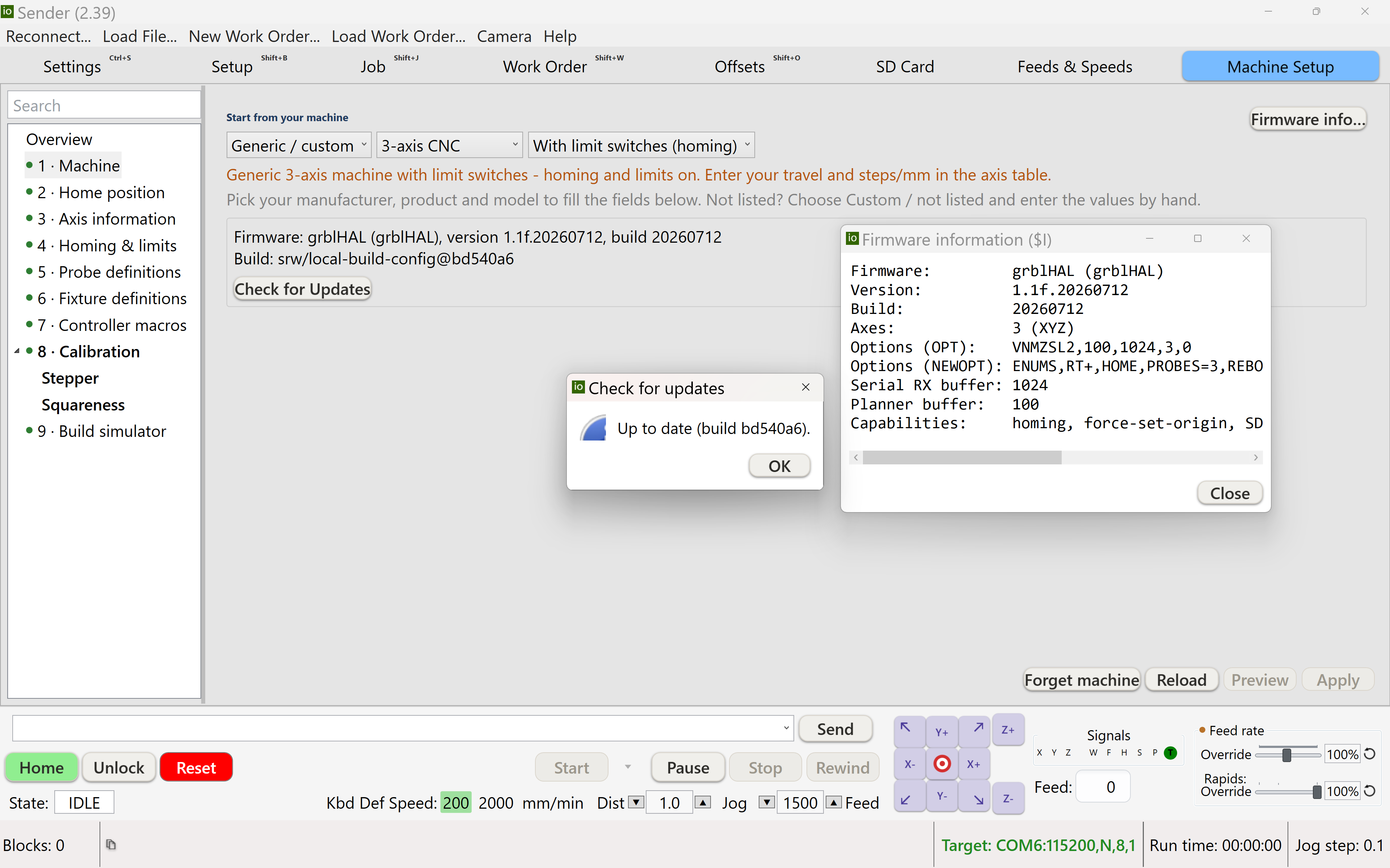
What you're looking at:
- The numbered steps down the left (1–8, plus Overview) are the guided sequence — work top to bottom; nothing is sent to the controller until you press Apply. It's the same searchable navigation tree as Settings, and each step carries a status dot — green done, orange needs attention, red not set — so you can see at a glance what's left.
- Start from your machine — three dropdowns let you pick a known manufacturer/product/model (or Generic/custom) so the later steps start from sensible defaults instead of blank fields.
- Firmware / Build — shows what's actually running on the connected controller right now; Check for Updates compares it against the latest published grblHAL build.
- Check for Updates compares the running build against the latest published grblHAL build — here it reports Up to date. When a newer build does exist you get a Firmware update available prompt instead, and Flash Firmware reprograms the board (this disconnects ioSender and needs the board's own RESET/PROGRAM button pressed within the time shown).
- Firmware information (the
$Iwindow shown here) — a read-only dump of the controller's reported firmware, version, build, axis count and enabled options — handy when reporting a problem. - Forget machine / Reload / Preview / Apply (bottom right) — Apply is the only button that actually writes settings to the controller; Preview lets you review the resulting
$settings first.
Machine Setup — a tab on the strip in a fresh install, and still a tab if you move it
into a menu, because it needs the run strip's Generate/Run button and jog pad — is a
guided wizard that walks you through the settings a new machine needs before it can safely home and run —
in plain-English steps instead of a wall of $ numbers. Do it once when you first connect a controller (and again after a firmware
reset). It writes real grbl settings to the controller's NVRAM, so it's how
you turn a blank board into your machine.
If setup isn't finished, ioSender opens straight on the first incomplete step — so you can't accidentally try to run a half-configured machine. Once all the steps are done, it stops nagging.
The eight steps
An Overview page lists them; each is a numbered entry in the tree that you complete in order.
| Step | What you set | grbl settings |
|---|---|---|
| 1 · Machine | Start from your machine — pick your machine so the later steps begin from sensible defaults instead of blanks. | — |
| 2 · Home position | The corner your machine homes to (front-left / front-right / back-left / back-right). Must match where your limit switches actually are — this is also machine origin. | $23 |
| 3 · Axis information | Per axis: travel, max rate, steps/mm, invert direction, limit-switch type and home direction. A Live column shows the controller's current value as you edit. Also Work surface (spoilboard) — see below. | $3 $5 $23 $1nn |
| 4 · Homing & limits | Enable limit switches, homing, force-origin and soft limits; set pull-off, locate/seek feed rates and debounce. | $27 $24 $25 $26 |
| 5 · Probe definitions | Declare the probes fitted to this machine (touch plate / 3D probe / toolsetter) so probing and Setup know what's available. | — |
| 6 · Fixture definitions | Define your own named workholding fixtures (a specific vise, fence, dog-hole grid…) that Setup can pick from, with a captured machine-coordinate reference position. | — |
| 7 · Controller macros | Install the controller-side macro set onto the controller's storage (e.g. Install ATC macros…). This step queries the controller to show what's installed or outdated. | — |
| 8 · Build simulator | Build a grblHAL simulator matching this machine's axes, probe and options — detected automatically, no picks needed — so you can test jobs offline (see Connect). | — |
It used to be step 8 here. It is now its own view at Tools → Calibration, holding four pages: Stepper calibration (probe) (corrects steps/mm by probing a reference block of known size against a validated Corner Fence for X/Y, and a 1-2-3 gauge block in three orientations for Z), Stepper calibration (scratch) (the same correction with a V-bit and calipers, needing no probe and no fixture), Squareness (pins) and Squareness (probe) (both correct gantry squareness on a ganged axis via
$170+). They moved because all four generate a program and run it, and that needs the
run strip — which exists only on the main window, so they have to open as a tab.Work surface — the board, not the travel (step 3)
Travel describes what the gantry can reach. The spoilboard is a different fact, and on many machines a smaller one: a toolsetter mounted off the front edge means the last stretch of Y travel is air the machine must keep being allowed to reach, or a tool change could never get to the puck. Step 3's Work surface (spoilboard) section is where you say so.
- Tick the spoilboard is smaller than the machine's travel and give the board's edges in machine coordinates — the same numbers the DRO shows with the spindle over each corner. Jog to a corner and read them off.
- Leave it unticked and the whole travel envelope is treated as board, which is exactly how the app behaved before this existed. A machine whose board does cover the table needs nothing here.
- Two features read it, and both of them raster a cutter across the whole thing: Work Order's Entire spoilboard Surface toolpath and the Height Map's Full work surface mode. Left undeclared on a machine where it isn't true, both run the cutter through open air at one end.
Controller macros (step 7)
Some of what ioSender does runs on the controller rather than being streamed to it — the tool change, the corner and centre probes, the tool-length reference. Those live as macro files on the controller's own storage, and step 7 is where they are installed and kept current. The step queries the controller and shows each macro as installed, outdated or missing.
- Only the macros that actually changed are sent. The files go up in small blocks and the controller commits each one to flash, so a full set is around twenty-three seconds. Editing one macro used to cost all of it; now it costs about three. (The comparison is per file and by content hash, not by size — an edit that happens to preserve the byte count is still an edit.)
tlo.macrois a required macro. It is newer than the others, so an existing installation will be offered an upload on the next visit to this step. Until you accept it, anything that references it — the tool-length reference, and the calibration wizards that end at the toolsetter — fails witherror:81, which is the controller saying it cannot find the file being called, not that anything is wrong with your machine.
Machine Setup reads the controller's settings the moment a page opens, and the controller's reply can land a fraction of a second later. A value that has not arrived leaves its field exactly as it was — it is no longer turned into a 0 — and the page quietly comes back for it a moment later rather than resting on one mechanism. Zero is a number an operator cannot tell from a measurement, and Apply on a page full of them would have written those zeros to the controller. If a page ever looked like it had "trashed" your setup on opening, this was why.
Why the order matters
The steps build on each other: you can't set useful soft limits (step 4) until the machine knows its travel and homing direction (steps 2–3); probing routines (step 5) need the axes configured; and the macros (step 7) assume a working, homeable machine. Calibration comes after all of it — it probes a fixture you defined in step 6 with a probe you declared in step 5. Working top-to-bottom once gets you to a machine that homes, respects its own limits, probes, and measures true.
Defining a fixture (step 6)
A fixture is a named piece of workholding — a specific vise, a corner fence, a dog-hole grid — plus a captured machine-coordinate reference position that Setup can probe against. The edit dialog is deliberately non-modal so the jog pad stays live while you're defining one:
- Set position captures wherever the machine currently is as the fixture's reference.
- Test rapids to the saved position and probes it. If you've since jogged somewhere noticeably different, it asks first and defaults to adopting where the machine actually is — otherwise pressing Test would silently undo your jog and re-run the identical failing probe. Nothing moves until you answer.
- The 3D Probe / Touch Plate choice is remembered per fixture. A touch-plate fixture reopens as a touch-plate fixture, so the next Set/Test can't quietly run with 3D-probe geometry and drop the plate thickness and lip offset. A brand-new fixture defaults by which probes you actually declared in step 5.
The recovery prompt tells you what went wrong and points you at Test. Jog closer to the feature, then press Test — it will offer to adopt the new position and probe from there.
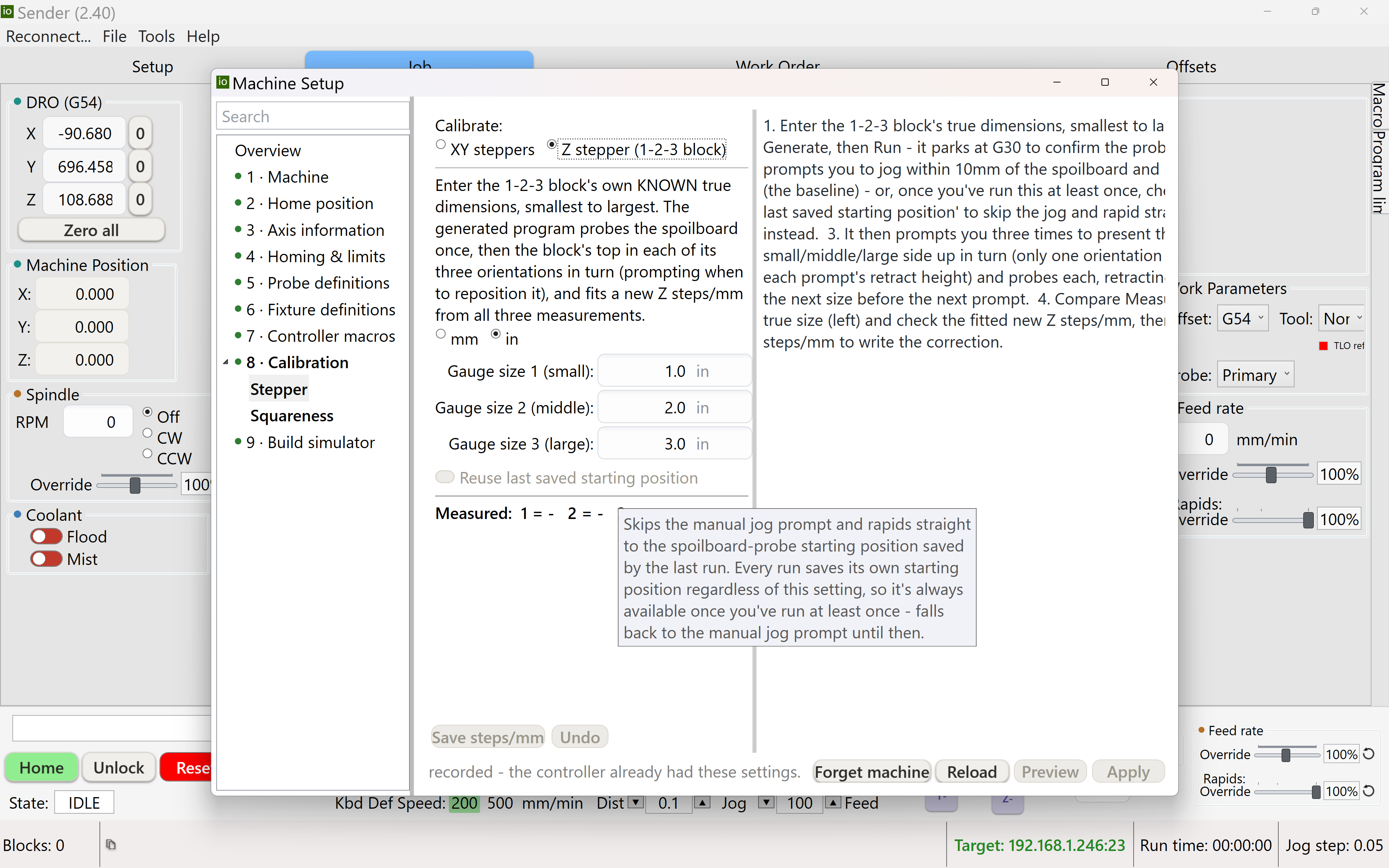
Stepper calibration and squareness started as standalone wizards on the old Tools tab, disconnected from the rest of commissioning; they were folded in here as a ninth step, and have now moved out again to Tools → Calibration — not a change of mind, but a consequence of what they do. All four generate a program and run it, and the Generate/Run button lives on the run strip, which exists only on the main window. See the callout above for where they are, and Accuracy & calibration for what the numbers mean.
Steps 2–4 describe physical reality — which corner homes, how far each axis travels, your drive type and switch wiring. If you're unsure, your machine's build documentation or the maker's default profile is the source of truth. Getting
$23 (home direction) or the limit-switch type wrong will make
homing drive the wrong way or fault.Machine Setup gets you safe and running. The Settings tab then exposes every
$ setting for fine-tuning, and Accuracy &
calibration covers dialing in steps/mm and squareness to a real dimension.Tools — the hardware-gated extras #
Three utilities depend on what your controller supports rather than on how you work. Each is its own entry at the bottom of the Tools menu, and each appears only when the connected board has the thing it tunes:
| Tools menu entry | What it does | Only if… |
|---|---|---|
| Tool table | Define your tools (number, diameter, length) so tool changes and offsets know each bit. | the firmware was built with a tool table (N_TOOLS non-zero) |
| Trinamic tuner | Tune Trinamic stepper drivers (current, StallGuard). | the board has TMC drivers |
| PID Tuner | Tune closed-loop / spindle PID. | the controller exposes a PID log |
On a hobby machine the common case is that your controller has none of the three, so none of them are listed — there is nothing to look for. There is no longer a "Tools" tab wrapping them: the wrapper is gone and the three tools stand on their own, so a board with just one of them shows just that one. Like any view, each can be moved onto the tab bar from Settings → User Interface → Top-level tabs.
Where the rest of it went
There used to be a Tools tab, a catch-all for machine utilities. Everything that wasn't hardware-gated has moved to where it's actually used, the standalone wizards were deleted rather than kept in two places, and what remained no longer needed a tab of its own:
| Used to be here | Now |
|---|---|
| Surface Spoilboard | A Surface toolpath in Work Order — same tool list, same feeds & speeds advisor, same generate/run path and dry run as any other operation. Its Entire Spoilboard mode is a checkbox on the toolpath. |
| Stepper calibration (manual / scratch / probe) | Tools → Calibration. The manual method is gone; probe and scratch are both offered — scratch needs no probe and no fixture, so it is the answer for a machine that has neither. |
| Auto Square | Tools → Calibration → Squareness (pins), beside a newer Squareness (probe) that measures the gantry against a reference square instead of sighting drilled pins. |
Height Map has a topic of its own — see Height Map. Probing does not: the standalone probing tab left the recommended workflow when Setup absorbed what it did, so that is where to read about probing, and where F1 from the Probing view takes you. The tab is still there for anyone who prefers the individual probe routines.
Work offsets (WCS) #
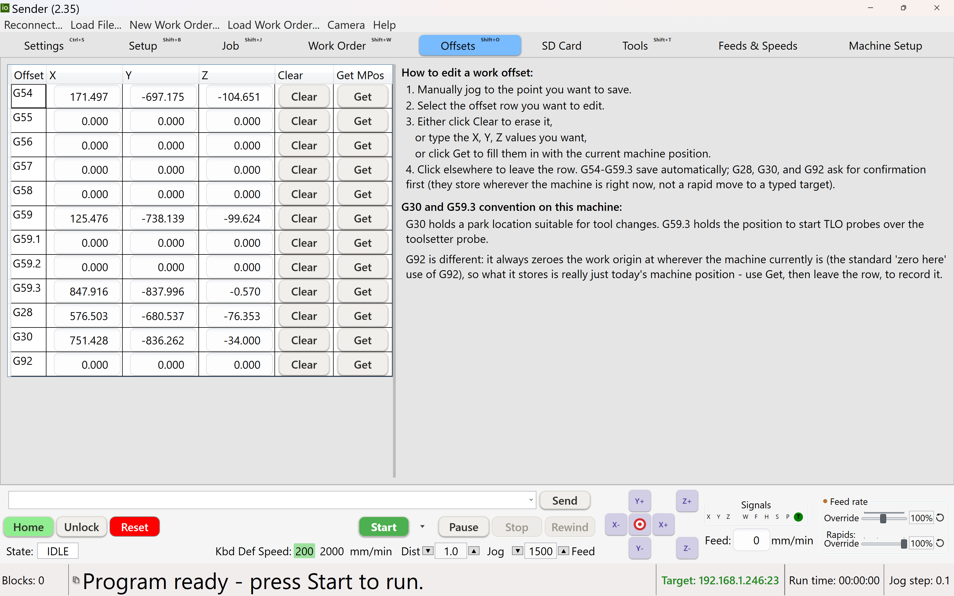
What you're looking at:
- Each row is one work-coordinate system (
G54–G59.3) or a system offset (G28,G30,G92) — your program runs in whichever one is currently active. - X / Y / Z columns are directly editable — type a value, then click elsewhere to leave the row and commit a plain
G54–G59.3change automatically. - Clr clears that one offset to zero immediately; Get copies the current machine position into the row's fields (still needs you to click away to commit it).
G28/G30/G92rows ask for confirmation before saving, since they store wherever the machine physically is right now rather than a typed number.- The explanatory panel (right) documents this machine's own convention for what
G30/G59.3are used for — worth reading, since these are just storage slots without a fixed meaning of their own.
A work offset is the stored gap between the machine's home and a work origin (see the
Intro diagram). grbl keeps several of them so you can have more than one setup
ready at once — the work coordinate systems G54 through G59.3.
Your program runs in whichever one is active (G54 by default).
The Offsets tab
It's an inline-editable grid, one row per offset (G54–G59.3 plus the system
offsets G28, G30 and G92). Every row edits and acts on itself —
there's no separate staging panel:
- Type directly into a row's X/Y/Z fields, then click elsewhere to leave the row —
a plain
G54–G59.3row saves automatically the moment focus leaves it. - Get — copy the current machine position into that row's fields (not written to the controller yet — still click away to commit it).
- Clr — clear that one offset (every axis to 0) immediately.
A changed-but-uncommitted value shows bold orange; a value that differs from what it was at startup shows blue — the same change-tracking convention as the Grbl settings tree. Right-click a row for Restore to value at startup.
The Go To actions (including a
G30 park) are machine-coordinate
moves, so they're only as trustworthy as the machine-coordinate reference — and ioSender now refuses to
run one on an unhomed machine. This isn't theoretical: after an unexpected controller reboot grblHAL
came back reporting Idle, not Alarm, with MPos:0,0,0 at wherever the tool happened
to be sitting. A G30 then chased its stored coordinates as a blind displacement from that
false zero and rapided into the hard stops. Soft limits are no backstop here — they're only enforced
once homed. Home first.Because these three store wherever the machine currently is rather than a typed target (no rapid move is ever issued), editing their row asks for confirmation before committing — click Get, then leave the row, to record today's position into one of them.
Most of the time you don't edit these by hand: Setup populates the active WCS for you when you zero on your stock. The Offsets tab is for reviewing them, nudging a value, or setting up a second fixture.
A stored offset is checked before the job, not discovered during it
A generated program declares what it needs before it runs — homed, a tool-length reference,
G30, G59.3. Each of those is checked for being set. The ones that name
a machine position are also checked for being reachable: a position recorded when the
homing pull-off was smaller, or before the travel settings changed, stays in the controller at a
coordinate the machine will now refuse to rapid to.
All of G28, G30 and G54–G59.3 are checked. If one
sits outside the soft-limit envelope, the run is refused up front, with the overshoot in
millimetres: "G59.3 is stored outside the machine's soft-limit travel: Y −884.5 is 24.5 mm
beyond the limit of −860.0. Move the machine inside its travel and set G59.3 again."
This is the check that turns a mid-run ALARM:2 — probe
fitted, tool in the work, job half done — into a dialog before anything moves. It only runs where it can
answer: soft limits on, the machine homed, and travel configured for that axis. Anywhere it cannot know,
it stays quiet rather than refusing a job that would have run perfectly well.
Under the hood, offsets are set with
G10 L2 (define a WCS in absolute machine
coordinates) or G10 L20 (define it so the current position equals given work
coordinates — what "zero here" does). A work rotation for skewed stock uses G10 L2 R.
See Accuracy & calibration → WCS discipline.G53 move right after a rotation writeAn active rotation does not contaminate a machine-coordinate move — grblHAL exempts
G53 from rotation, so there is no need to clear the rotation before one, and the
R0-before-G53 habit this page used to advise is worse than
useless: an R0 is itself a rotation write, and that is the thing to be careful
about.Writing the rotation of the coordinate system that is currently active — setting it, clearing it, or restating it — leaves the firmware's parser holding a corrupted position, and the next move that leaves an axis unnamed flies to whatever that corrupt value says. A bare
G53 G0 Z0 "safe lift" is exactly such a move, and on a real machine one has
traversed the entire table at rapid. It does not even need an R word: a plain
G10 L2 P1 X0 Y0 Z0 against a WCS that merely has a
rotation is enough.ioSender repairs this in every program it generates — each rotation write is followed by a dwell and an absolute move naming X and Y from the machine's own stepper position, which overwrites whatever the parser believed. If you write
G10 L2 by hand at the MDI, or in a macro of
your own, do the same: follow it with a move that names the axes rather than a Z-only lift.
A G53 Z-only lift is not a safe lift on its own.Settings — grbl & app #
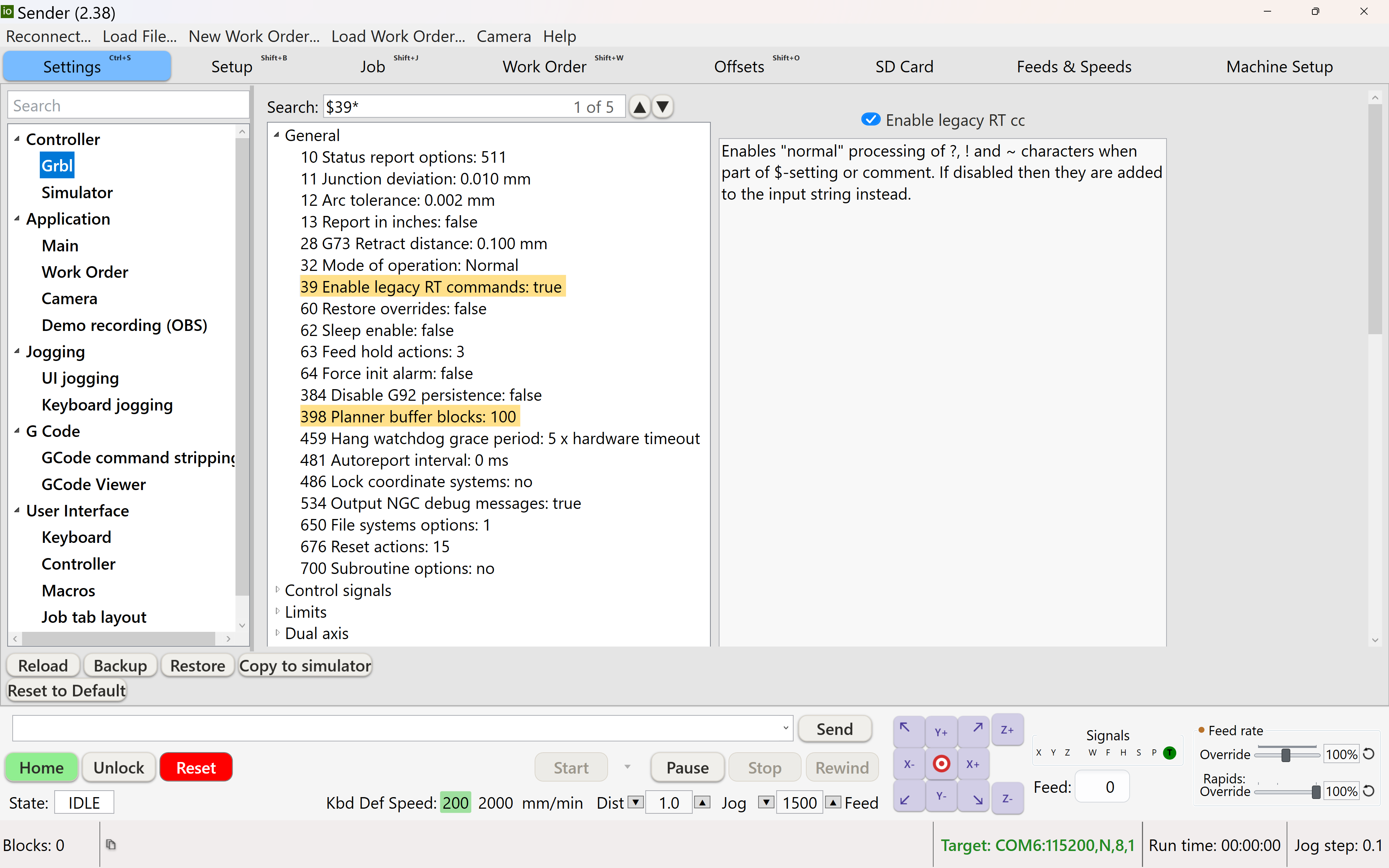
What you're looking at:
- The navigation tree (left) lists every settings page grouped into five categories. Pick a page; it opens on the right. There are no tab strips.
- The Search box above the tree filters it live and reports a match count. It searches the words on each page, not just page names — "backlash" finds Axis information, "OBS" finds Demo recording.
- The page area (right) shows one config panel at a time, with room to breathe — panels are no longer crammed two or three to a column.
- Save / Restart / Reset to Default (bottom) is a shared footer; which buttons appear depends on the page (Reset only shows where the page actually has resettable settings).
- On the Grbl page specifically, the footer gains Reload / Backup / Restore / Copy to simulator — Backup/Restore snapshot and roll back a whole settings set; Copy to simulator pushes the same settings into the bundled offline simulator so it matches your real machine.
Settings — the first tab on the strip in a fresh install, or wherever you have moved it to — holds the controller's settings plus ioSender's own preferences, in one place. They're organised as a tree of five categories:
| Category | Pages |
|---|---|
| Controller | Grbl — every $ setting the controller has, with its own group tree and $-search (see below). Simulator — build and manage the bundled option-matched grblHAL simulator (see Connect and Machine Setup), also reachable at startup via the -simulator command-line flag. |
| Application | One page per panel — Main is how ioSender talks to the controller (reset delay, poll interval, buffer size and aggressive buffering, comment/line-number handling, prefer-network-if-available, and the grbl auto-save pair), plus Work Order, Camera and Demo recording (OBS). How the app itself looks and behaves is not here — that's User Interface → General, below. |
| Jogging | UI jogging and Keyboard jogging — jog steps and feeds for each, and mirroring them to the controller's firmware jog ($5x). See Jogging. |
| G Code | GCode command stripping (what gets filtered on the way out) and GCode Viewer (how the 3D view draws it). |
| User Interface | General — how the app itself looks and behaves: keep MDI focus, restore the last window size, friendly Start/Pause run-strip labels, UI scale, the go-to buttons on the jog pad, ESC closes current tab if closable, Show 3D view in split screen on Job tab, the status pop-up dwell slider, and the app's own auto-save / prompt-before-saving pair. Then Keyboard and Controller (game-controller bindings), Macros, Job tab layout, and Top-level tabs. |
Four in User Interface → General worth knowing about
- Dismiss pop-up status window after n seconds. The Status window opens itself only for an error or an alarm — every other message is recorded quietly — and this slider (1–60 s) is how long it lingers before dismissing itself. Shortening it loses nothing: nothing is ever dropped from the log behind the Status button. A window you opened never closes on its own.
- ESC closes current tab if closable. Off by default. Only a tab opened from the File or Tools menu is closable — one you placed on the tab bar yourself stays, since closing it would leave no way back to it. Esc keeps all its other jobs either way: it still dismisses a dialog, cancels an edit in a text box, and cancels a handed-off program before it closes anything.
- Show 3D view in split screen on Job tab. Program list and 3D view side by side with a draggable splitter, instead of a tab strip that switches between them — see the Job screen for what gives up the space.
- Continuous jogging — hold to jog lives under Jogging → UI jogging. It is the same selection the old on-screen jog panel's Continuous radio used to make; when the abbreviated jog panels dropped that radio, the mode stayed reachable in code and persisted on disk with nothing anywhere to turn it on. There is a Continuous tick on the run strip's Jogging group too, and they are the same switch. A tap still moves one step either way, and Shift/Ctrl+Shift jog continuously regardless of the setting.
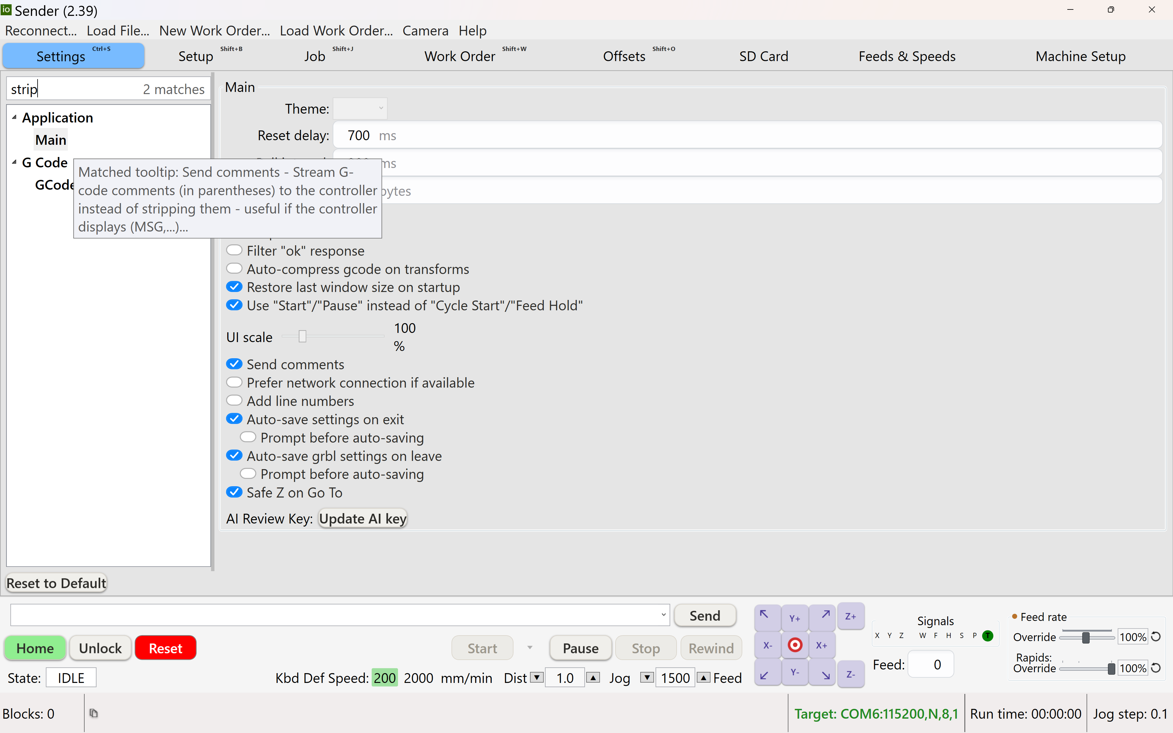
A lot of ioSender's useful text lives in tooltips, so search will sometimes land you on a page where nothing visible matches what you typed — exactly what Main does in the shot above. Hover the matched entry's label in the tree and it tells you why it matched: Matched text: … or Matched tooltip: …, quoting the words it hit and, for a tooltip, naming the control they belong to. So the answer isn't just "it's on this page somewhere" — it's "hover Send comments". A correct match never has to read as a wrong one.
Open the page and the search goes one further: every control that matched is outlined on the page itself and the first is scrolled into view, so you are not left reading a settings page hunting for the word. An outline drawn dashed means the match is in that control's tooltip rather than in anything visible — the same "hover me" it always was, now marked where the control actually is.
Inside the Grbl page you still get the familiar group tree and
$-search —
a wildcard like $39* or free text like "jog", with next/previous match arrows, change
highlighting for settings altered since startup, and right-click to revert one. That's deliberately
not lifted into the navigation tree: those are live controller settings, fetched on connect and
absent entirely on classic grbl, so the tree would change shape whenever the machine connected.Machine Setup is the guided subset that gets a new machine running; the Grbl page here is the full list for fine-tuning. The auto-save / prompt-on-save options control whether changes are written to the controller immediately or after confirmation.
Restore points — going back to a moment
ioSender snapshots two different things as you work: the controller's
$ settings, and its own configuration — profiles, probe and fixture
definitions, the work surface, the layout. Both land in the same backup folder with the same timestamp,
and Restore, on the Grbl page, lists them as what they are: moments.
- Each entry says when it was taken, how long ago, and what it holds — one of the two, or both.
- You then choose what to put back: machine settings, app configuration, or both.
- That ordering is the point. "It was fine an hour ago" is a statement about a time, and the old list asked you to already know which kind of file held the thing that broke — which is the thing you are trying to find out.
Configuration overlays
An overlay is a fragment of a configuration — a .ioconfig file
holding just some of the sections a full App.config has. Layering one lets you adopt a
specific change, most usefully somebody else's screen layout, without touching your machine
settings, profiles, fixtures, macros or keymaps. It exists because an upgraded install keeps its own
saved layout forever: without this, a new arrangement can reach a new installation and never reach
yours.
All three commands live under Help → Support:
| Command | What it does |
|---|---|
| Apply configuration overlay… | Layers a .ioconfig
onto this profile. It backs the current configuration up first and restarts ioSender
to apply it; afterwards it tells you which sections it actually took. |
| Export configuration overlay… | Writes your screen layout out as
a .ioconfig somebody else can apply. Machine identity is never included
— not the port, the network host or the machine itself. |
| Undo configuration overlay | Puts the configuration back exactly as it was immediately before the last overlay. Restarts too. |
A section can be layered in one of two ways: replace, the default, where the overlay's copy supplants yours wholesale — what a layout wants — or merge, where only the fields the overlay actually carries are grafted onto yours, so a fragment can flip three settings without carrying all eighty. There is no separate overlay format to learn: an overlay is a working configuration with the sections you don't want deleted.
Starting ioSender with
-overlay <file> applies the overlay for that launch
only — the way to see what a layout does before adopting it. It is transient in a strong sense:
for that run every save is diverted to a side file, so nothing the session does can write the
overlay into your real profile. Relaunch without the flag and you are back exactly where you were.Two more under Help → Support
- Restart ioSender… sits alone at the top of the menu because it is a recovery action, not a convenience: it saves your settings, closes and reopens, which clears anything held only in memory for this session — a stuck connection state being the usual reason to reach for it. It asks first.
- Machine mirror, under Tools, is a read-only live view of the machine state as seen through the client/server wire protocol. It is a developer's diagnostic: any disagreement between it and the main window is a protocol bug.
The Camera menu only appears once a device is bound: go to Settings → Application → Camera, pick a device from the dropdown and Connect.
A keyboard shortcut names a view, not a place. Bind a key to Probing and it works whether Probing is a tab on the bar or an entry in the Tools menu — the same key shows it either way, so moving a view around never costs you its shortcut.
Where each view lives
Settings → User Interface → Top-level tabs lists every view with a destination beside it: Tab bar, File menu, Tools menu, or Not shown. A fresh install ships the full tab bar — nine tabs — and this is how you slim it down: move the views you don't want on it into a menu, and restart. That way round on purpose, because a saved layout is never overwritten by an upgrade: a crowded default you can cut back beats a slim one nobody can opt out of. Move Offsets into a menu, put Probing on the bar, hide what you never touch. The ▲▼ buttons set the order within whichever destination a view is assigned to (left to right on the bar, top to bottom in a menu). Changes apply on restart — and a layout you like can be handed to someone else as a configuration overlay.
Settings, Machine Setup and Job can be moved between the bar and a menu but not hidden — ioSender puts them back rather than let a layout lock you out.
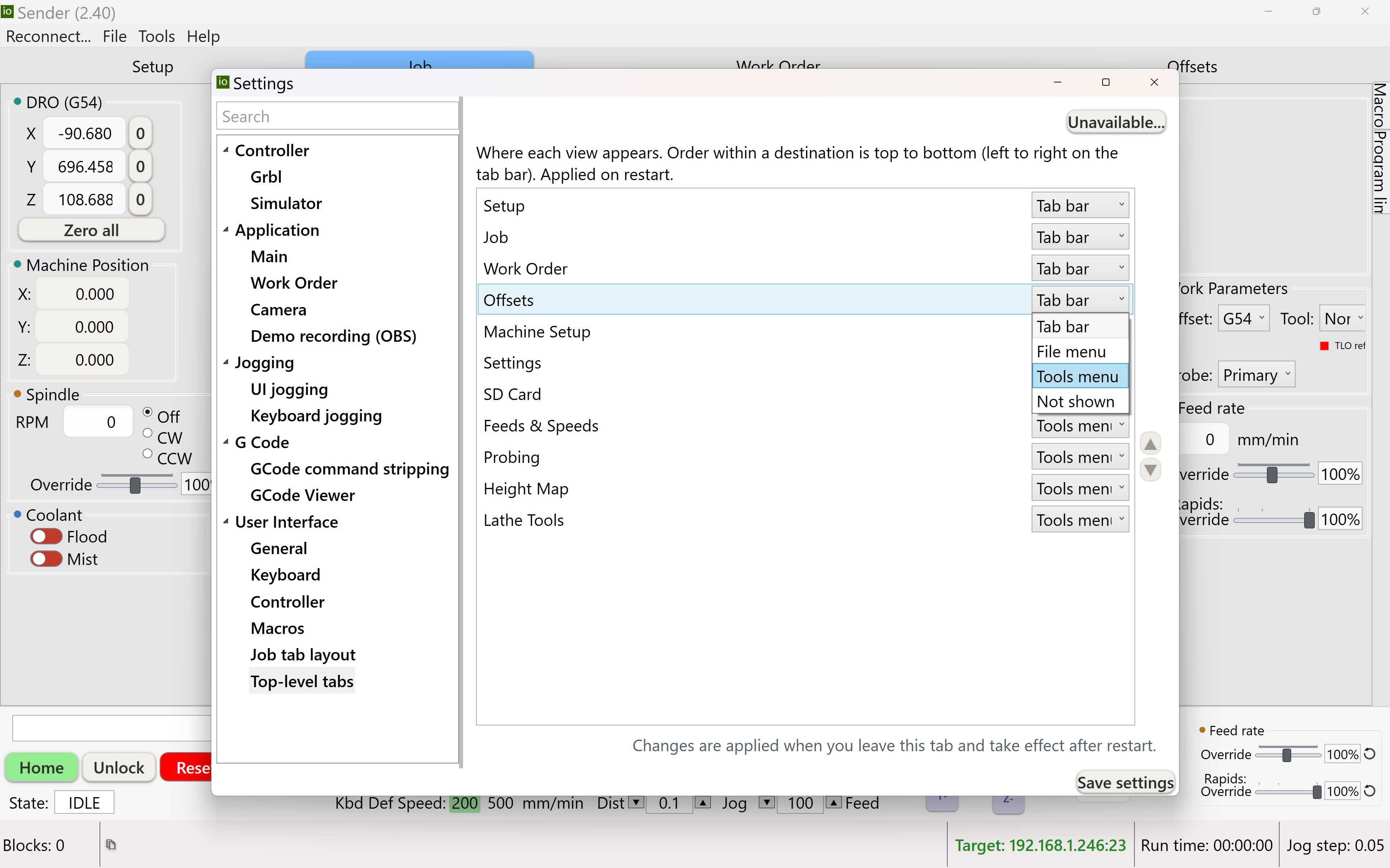
Binding a key to a tab or menu entry
Settings → User Interface → Keyboard groups these three ways:
| Group | Holds |
|---|---|
| Top Level Tabs | The views — Job, Setup, Offsets, Probing, Settings, Machine Setup, the tool and tuner windows… Anything that can sit on the tab strip. |
| Top Level Menu Items | The built-in main-menu commands, which are not views and cannot be placed on the strip — Connect, the File entries, the Help entries. Listed immediately above the tabs, because they're related; kept separate, because a tab can be moved and a File command cannot. |
| Program | Three run-strip buttons: MDI
(opens the console with the caret in its input box), Status (the message history) and
Peek / Resume (park at G30 and look at the work — see
Peek). These are the ones worth reaching without the mouse, and unlike the menu
commands they stay live during a run — which is exactly when you want them. That is
also why Peek is here and not on a menu: the menu bar is disabled while a job streams. |
All start unbound. Sub-pages within a view — a particular Settings page or Machine Setup step — are deliberately not bindable; shortcuts address top-level destinations only.
A shortcut for a menu command is refused whenever that entry is greyed out, so a key can never do something the menu itself is currently refusing. The same holds for the two run-strip buttons: the key presses the actual button, so it can't drift from what clicking does, and it's refused while the button is disabled.
Keeping ioSender up to date
Help → Support → Check for updates... checks GitHub for a newer released version and walks you through installing it (on a dev build, it instead offers a dropdown of every published release to switch to). If an update is found in the background, the window's title bar quietly appends "(update available)" as a hint, without interrupting anything. Roll back to previous version... swaps back to the build installed before your last update — it only remembers one step back, so it won't work if you haven't updated at least once yet.
Feeds & Speeds (Fusion 360 Addin) #
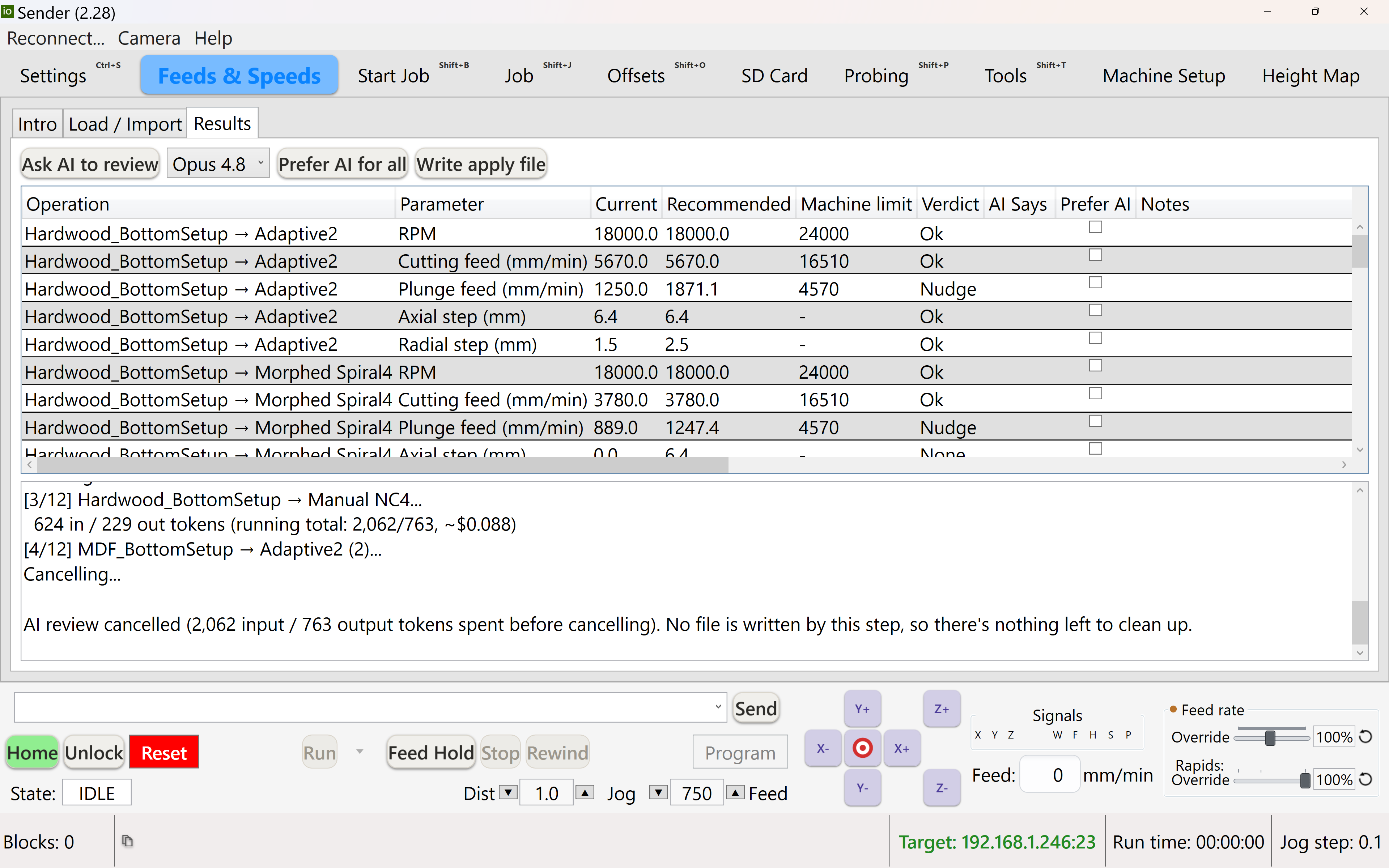
What you're looking at:
- Ask AI to review / model dropdown — sends every operation to the picked AI model for a second opinion; nothing is applied automatically.
- The grid — one row per operation and parameter (RPM, feeds, step-overs); Current is what Fusion exported, Recommended is the table's own chip-load-based number, Machine limit is your connected controller's actual ceiling, and Verdict flags whether it's fine (Ok), worth a small correction (Nudge), or should Change.
- AI Says / Prefer AI — once a review runs, the AI's own opinion appears per row; tick Prefer AI (or "for all") to use its number instead of the table's.
- Write apply file — saves only the flagged rows to a companion file Fusion reads back in.
- The status log (bottom) is a running transcript of the review — including cost/token counts. This particular capture shows a review being cancelled partway through (Esc/Ctrl+C), which is why it reads "Cancelling…" / "AI review cancelled".
The ioSenderV2 Fusion Addin adds an "ioSenderV2" panel to Fusion 360's Manufacture workspace with Feeds and Speeds and Batch Post Process commands. The matching Tools → Feeds and Speeds view in ioSender reviews what Fusion exports against a material chip-load/surface-speed table and your connected controller's actual machine limits, before you post any g-code — no controller connection required, it works entirely offline against the export file.
First-time setup
- In ioSender: Help → Support → Install ioSenderV2 Fusion Addin... (only shown when Fusion 360 is installed for this user) — symlinks the add-in into Fusion's AddIns folder, so future ioSenderV2 updates need no reinstall.
- In Fusion: Utilities → ADD-INS → Scripts and Add-Ins → Add-Ins tab, select ioSenderV2, click Run (tick Run on Startup so it's always available).
Workflow
- In Fusion's Manufacture workspace, run the ioSenderV2 panel's
Feeds and Speeds command — it exports the current setups/operations automatically
(to
~/Downloads/ioSenderV2/<docName>.json) and leaves its dialog open. - Switch to ioSender's Feeds & Speeds tab, Load / Import
sub-tab, click Load latest export. Pick a Material — the default,
Derived, reads each setup's own material from its name (a prefix like
MDF_...orMaple_...); choosing a specific material instead overrides every operation to that one material regardless of setup name. - A successful load jumps straight to the Results tab: one row per operation and
parameter (RPM, cutting feed, plunge feed, axial step, radial step), each showing Current,
Recommended, Machine limit (cross-checked against the connected
controller's
$30max RPM and$110-$112max feed rates) and a Verdict (Change / Nudge / Ok). - Optional: Ask AI to review (only shown once an AI review key is set — Settings → App → AI Review Key) sends every operation to the selected model for a second opinion, filling in an AI Says column and a running cost/token estimate. It never applies anything by itself — tick Prefer AI on a row (or Prefer AI for all) to use its number instead of the table's when you write the apply file.
- Click Write apply file — writes a companion
-apply.jsonnext to the export containing only the rows flagged Change (or explicitly Prefer-AI-overridden), and archives a copy of both files under the app's logs folder (Fusion deletes its own copies once its dialog closes, so this is the only lasting record of what changed). - Back in Fusion — with the Feeds and Speeds dialog still open — choose Action → Apply (or press OK) to pull the changes into your operations.
- Use the ioSenderV2 panel's Batch Post Process command to post multiple
setups/operations to g-code files in one action — handy after duplicating a setup for a second
material (e.g. a
Maple_setup copied toMDF_) once its feeds and speeds have been recalculated.
Chip-load and surface-speed reference values per material come from published carbide bit charts (Onsrud/Amana/Vortex-style starting points), then clamped to what your connected controller can actually do. The optional AI pass is a second opinion for you to read, not a replacement for the table.
SD card jobs #
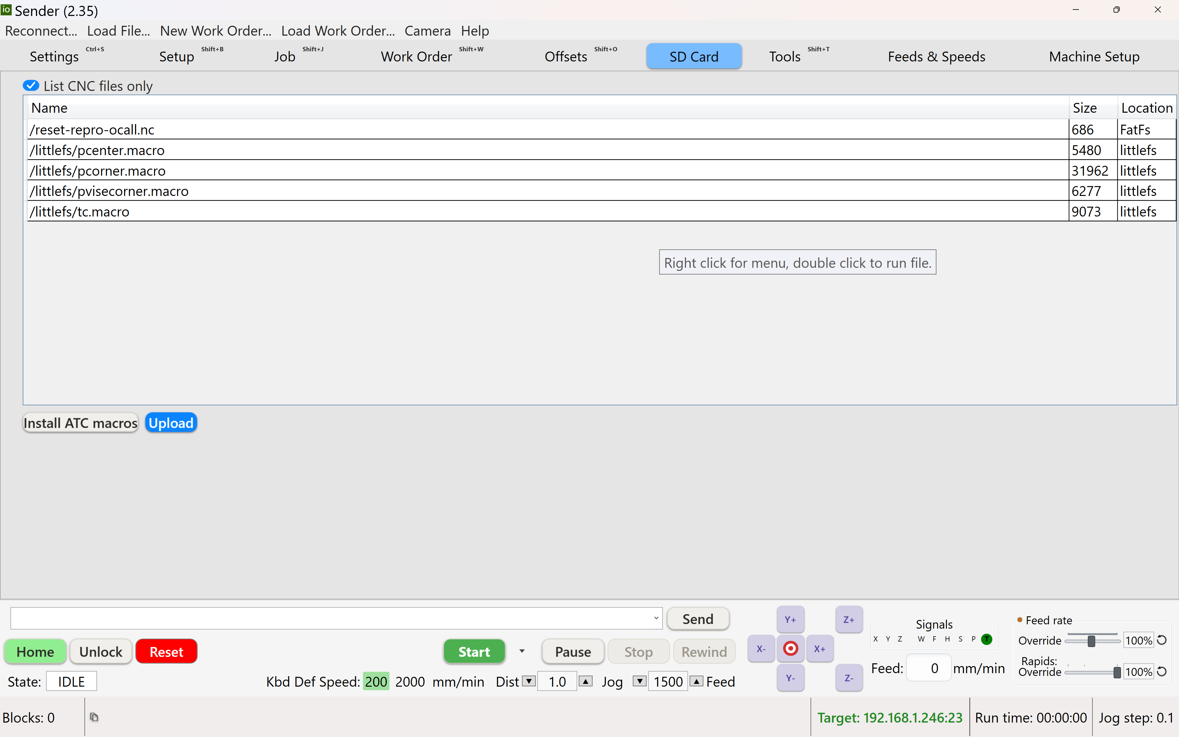
What you're looking at:
- The file list shows what's actually stored on the controller's own SD card / flash (not your PC) — Size and Location (e.g. FatFs vs littlefs) columns show where each file physically lives on the controller.
- List CNC files only filters out non-g-code files (like the
.macrofiles shown here) from the view. - Upload copies a file from your PC onto the card; Install ATC macros pushes the controller-side macro set (the same one Machine Setup step 7 installs).
- Selecting a file (not shown open here) offers Load and run / Edit / View / Delete / Move / Copy.
Many controllers have an SD card (or onboard flash) that stores g-code files on the controller itself. Tools → SD Card manages those files and can run them directly.
- Upload / From file — copy a local g-code file onto the card.
- Load and run — run a file straight from the card: the controller streams it itself, so the job keeps going even if the USB link or ioSender hiccups. Great for long jobs.
- Manage — Create, Edit, View, Delete, Move and Copy files; a List CNC files only filter; and an Enable rewind option.
The controller-side macro set (e.g. Install ATC macros) lives on this storage too — the same set Machine Setup step 7 installs. Installing is now per file and hash-compared: only the macros that actually differ are sent, so editing one costs seconds rather than the whole set. And the upload no longer crawls — it used to run at one packet per status poll, turning a six-second transfer into fifty-six.
A listing the controller never answered — because it was busy homing, say — used to come back empty, and empty was then reported as fact: no macros found, on a controller that had them. Unknown is now distinct from empty and is reported as unknown. If you see that, the answer is to ask again once the machine is idle, not to reinstall anything.
The 3D g-code viewer #
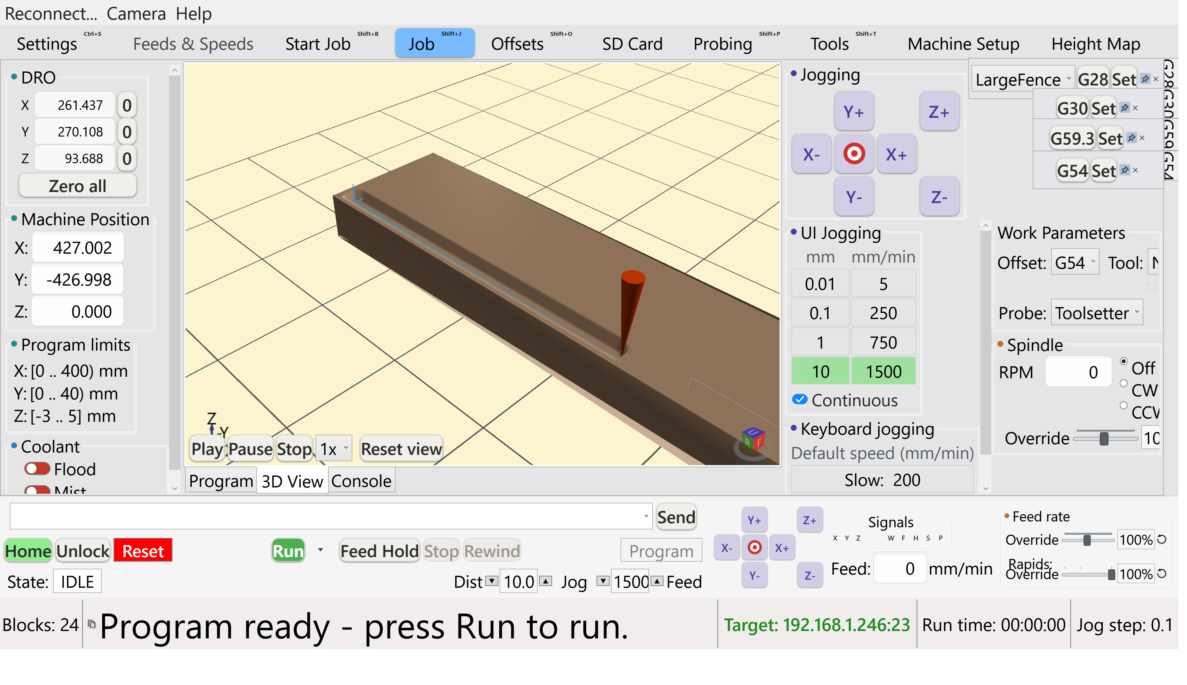
What you're looking at:
- The 3D pane itself sits between the DRO panel and the jogging controls on the Job screen (see The Job screen) — this shot shows it mid-program, with the toolpath already carved into the stock model.
- Play / Pause / Stop and the speed dropdown (1x) play back the toolpath animation at the chosen speed without actually running the machine.
- Reset view snaps the camera back to fit the whole scene; the small cube gizmo in the bottom-right corner (the ViewCube) can be clicked to snap to a specific face.
- The orange cylinder is the cutting tool's current position; the brown block is the stock, shown at its real probed size.
The 3D viewer sits beside the g-code list on the Job screen and draws the entire toolpath before you cut — so you can sanity-check a program, see where it sits on your stock, and watch progress as it runs.
Getting around
- Drag to rotate, scroll to zoom, and use the ViewCube to snap to a face.
- Reset view (Ctrl+V) re-fits the machine/program; Save view stores the current angle as your default.
What you can show
Toggle the grid (Ctrl+G), X/Y/Z axis markers, the work envelope (your machine's travel), the program's bounding box, the coordinate system and a text overlay. Colours for cuts, rapids, retracts and the highlight are all configurable, and Highlight completed cuts shows how far a running job has got.
Hold Ctrl and click a point in the view to jog there — the machine raises Z to a safe height first, then rapids to the spot. A fast way to reach a feature without nudging with the jog keys.
The stock block, and what it is drawn from
The block the toolpath carves into is not a decoration — it is a real dexel model, and it is drawn from what the program actually says:
- Where the program declares its stock (a Work Order does, and a Fusion post can), that is exactly what you see: the declared board, in the declared place. Not a box grown to fit the toolpath — a 368 × 232 board once rendered as a block the size of the lettering on it.
- The thickness comes from cutting moves only. Rapids, the machine-coordinate
preamble every generated program opens with, and probe moves are all excluded. A 6.35 mm board
used to be drawn about 80 mm thick, because a
G53park at the top of travel was being read as material. - Where no size is known at all — nothing declared, and no cutting move to infer a thickness from — the view says "No stock size information" and draws no block, rather than inventing a plausible-looking slab that would misrepresent every depth in the program.
G53moves are drawn in the right frame. A machine-coordinate park no longer leaks into the work-coordinate picture — which is also what used to make a 32 mm job report an 858 mm span to the travel check.
To start a job partway through — from a chosen toolpath, or a chosen line — use the program list's right-click menu on the Job screen, not this view.
Lathe mode & wizards #
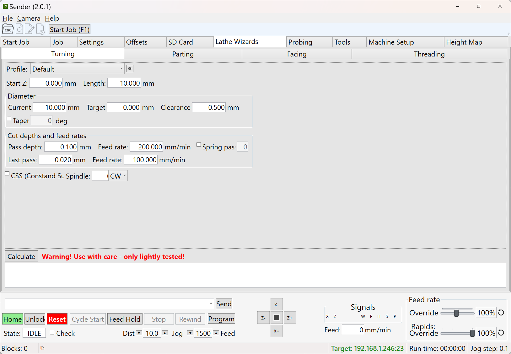
What you're looking at:
- Profile — a saved set of defaults for this wizard (bit geometry, preferred depths) so you don't re-enter them every time.
- Start Z / Length / Diameter (Current/Target/Clearance) — the geometry of the cut: where it begins, how far along Z it runs, and the diameter it starts and ends at.
- Cut depths and feed rates — per-pass depth and feed for the roughing passes, plus a separate, lighter Last pass for the final finish pass.
- CSS (Constant Surface Speed) — holds a constant cutting speed at the tool tip by varying spindle RPM as the diameter changes, instead of a fixed RPM.
- Calculate generates the actual turning program from these numbers, ready to load and run like any other g-code.
ioSender also drives lathes. There is no app switch to throw: lathe mode follows the
controller — a firmware built with lathe support reports it (LATHE in its
$I options) and the interface switches to a lathe layout, with X as the diameter/radius axis
and Z running along the spindle. The wizards live at Tools → Lathe Tools.
The wizards
Rather than hand-writing turning g-code, fill in dimensions and let a wizard generate the program:
| Wizard | Operation |
|---|---|
| Turning | Reduce diameter along a length. |
| Facing | Clean up the end of the stock. |
| Parting | Cut the finished part off. |
| Threading | Cut a thread. |
Each produces a normal program that loads and runs on the Job screen like any other.
Errors & alarms #
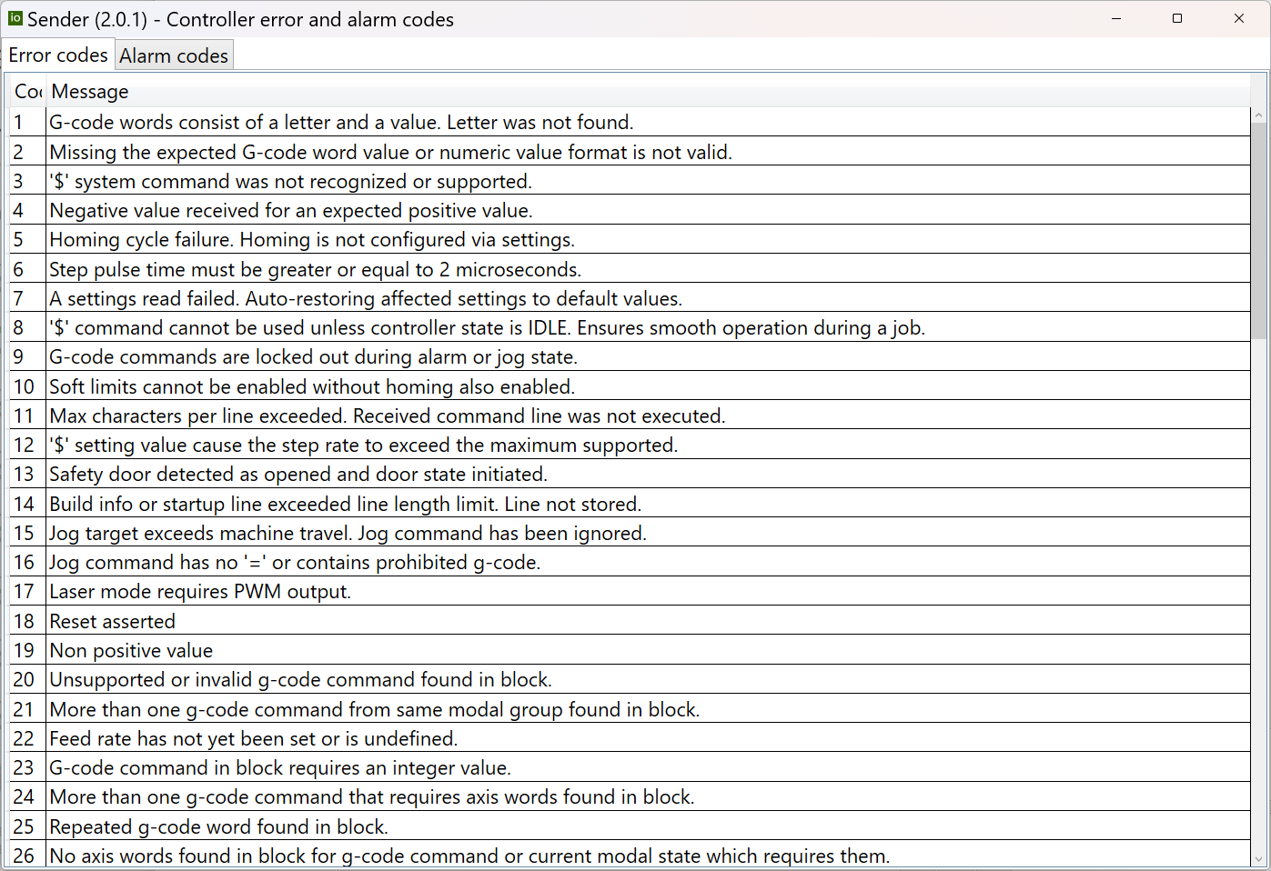
What you're looking at:
- Two tabs — Error codes and Alarm codes — each a plain-English lookup table for every numbered code the controller can report.
- Find the code the machine reported — from the pop-up Status window, or the status log — in this list to see exactly what it means (and, for alarms, what usually causes it).
- This reference opens from the Help menu any time, even without a job running — handy to have open the first few times you hit an alarm.
Sooner or later the machine stops and shows a code. Don't panic — grbl is just telling you what happened. There are two kinds, and they mean very different things.
An error rejects a single command and tells you why (bad g-code, a setting that isn't allowed right now). The machine keeps its state; fix the command and carry on.
An alarm means something unsafe happened — the machine locks out motion until you deliberately clear it. Position may no longer be trusted.
Clearing an alarm
- Soft-reset (the Reset button) to stop and acknowledge.
- Unlock with
$Xonly once you've checked it's safe to move. - Home (
$H) to re-establish position — the proper way to recover after a limit trip or a reset during motion.
Common alarms
| Alarm | Meaning & usual cause |
|---|---|
| 1 | Hard limit tripped — a limit switch was hit. Re-home. |
| 2 | Soft limit — a commanded move would exceed machine travel. Usually a bad work origin or a program too big for the stock position. Two specific causes ioSender now catches before the run: a stored WCS origin sitting outside the travel envelope, and a program whose footprint is bigger than the machine. If one of those is your cause, you get a dialog at the start instead of an alarm halfway through. |
| 3 | Reset while in motion — position lost. Re-home. |
| 4 / 5 | Probe failed — didn't start where expected (4) or didn't make contact within travel (5). Check wiring and the probe. |
| 6–9 | Homing failed — reset during homing, or a switch wasn't found. Check switch wiring and pull-off. |
Common errors
| Error | Meaning |
|---|---|
| 1 / 2 | Bad g-code word or number format — often a stray character or an unsupported command. |
| 8 | A $ command was sent while not idle — stop the job first. |
| 9 | G-code locked out — the machine is in an alarm or jog state. Clear the alarm (above) first. |
| 15 | A jog would exceed travel — jog a smaller distance. |
| 20 | Unsupported or invalid g-code command for this controller. |
Help → Error and alarm codes opens a searchable dialog with every code your controller defines — the authoritative reference for anything not in the short lists above.
The window that popped up to show an error dismisses itself after a few seconds, and an error is often followed by three more before you look up. The run strip's Status button reopens it with the full history since launch. Nothing is ever dropped from it, and every message is also written to
%AppData%\ioSender\logs\latest_status.log as it happens,
tagged with whether it came from ioSender or from the controller itself as an [MSG:] —
which is the question this log gets opened to answer. See
the Status window and the log.A soft-limit alarm (2) or a jog-travel error (15) usually means your work origin or travel is wrong — unlocking and re-running will just crash into the same wall. Fix the cause: re-check your origin or travel/homing setup first.